Research
, Volume: 21( 1) DOI: 10.37532/0974-7443.2026.21(1).001Geopolymer Formulations for Radioactive Waste Disposal Applications: Scale-Up to 100 Kg Blocks
- *Correspondence:
- RD Ambashta
Nuclear Recycle Group, Bhabha Atomic Research Centre, Mumbai, India
E-mail: aritu@barc.gov.in
Received: March 29, 2026, Manuscript No. TSCT-26-187181; Editor assigned: April 01, 2026, PreQC No. TSCT-26-187181 (PQ); Reviewed: April 15, 2026, QC No. TSCT-26-187181; Revised: May 29, 2026, Manuscript No. TSCT-26-187181 (R); Published: June 08, 2026, DOI. 10.37532/0974-7443.2026.21(1).001
Citation: Ambashta RD, et al. Geopolymer Formulations for Radioactive Waste Disposal Applications: Scale-Up to 100 kg Blocks. Chem Tech Ind J. 2026;21(1).001.
Abstract
Geopolymerisation is a promising matrix as an engineered barrier for radionuclide disposal. This study, besides optimisation of parameters for preparing a good geopolymer matrix for radionuclide immobilization utilising industrial wastes such as Fly Ash (FA) and Ground Granulated Blast Furnace Slag (GGBFS), mainly focuses on scale-up geopolymer blocks to 100 kg blocks (perhaps the first time!), required for actual immobilization at plant sites. The paper discusses the details of the formulations, characteristics of the large geopolymer blocks vis-à-vis lab-scale products, the challenges and their experience in the scale-up process, and the way ahead towards the realization of geopolymers at the industrial level. It is to be noted that the precursors used in the process, fly ash and BF slag, are secondary (not virgin) resources and are environmentally friendly. The studies reveal that the characteristics suit the intended application.
Keywords
Radioactive waste immobilization, Geopolymer, Porosity, Hydraulic conductivity, Scale-up, Isothermal conduction calorimetry
Introduction
Nuclear energy is an option for the energy sector to limit carbon emissions in line with the Paris Declaration; as a source of clean energy (after hydropower) its current share of nuclear power (10%) is expected to increase as more units are in the offing [1]. It is estimated that nuclear energy can abate many million tonnes of carbon dioxide emissions [2]. The problem with nuclear power reactors is their wastes, which are generally radioactive. Safe disposal of nuclear waste is of prime importance to protect living beings and the environment and prevent migration to other geographic locations. With increasing nuclear based power plants, radioactive wastes are bound to increase.
Chemical bonds in OPC matric, viz. van der Waals and hydrogen bonds, are prone to crack under pressure. For several reasons like this, repalcement of the currently used Ordinary Portland Cement (OPC)-vermiculite based matrix is under active consideration for better matrices. For radioactive waste disposal applications. Among systems considered for replacing OPC-based immobilization, geopolymers have advantages in terms of chemical durability, high strength, presence of nano zeolites for holding the radionuclides by ion exchange, etc. Geopolymers or inorganic polymers are formed from the polycondensation of mineral raw materials containing aluminosilicates, forming a resistant chemical structure. van Jaarsveld et al., report that immobilization in geopolymers is by physical entrapment (in a better-packed, less porous structure) or chemical bonding. Geopolymer forms when aluminosilicates (or oxides of alumina and silica) react with alkali hydroxide/alkali silicate solution; the general molecular structure describing geopolymers is:
Mn [–(Si–O2)z–Al–O2]n . wH2O (1)
(where M is an alkaline element, the symbol '–' indicates a bond, z is 1, 2, or 3, and n is the degree of polymerization). Besides its enhanced strength arising from its three-dimensional [Si–O–Al–O]n framework, unique microstructure, consisting of Si and Al tetrahedral units forming a closed cage cavity, can immobilize/ trap radionuclides [3].
Unlike cement-based mortar preparation, geopolymer preparation uses alkali hydroxides and silicates instead of water; hence, there are associated challenges. The challenges are ensuing from the viscous and corrosive nature of the alkalies. One needs to ensure workability, proper compaction, and sufficient setting time (to avoid premature setting) while eliminating excess usage of chemicals. A recent paper describes the mechanisms, challenges etc. of geopolymer in nuclear waste storage and immobilization [4]. Another paper explores sewage sludge ash as a precursor for management of radioactive wastes [5].
This paper describes a part of the studies by CSIR-National Metallurgical Laboratory (CSIR-NML), Jamshedpur and Bhabha Atomic Research Centre (BARC), Trombay on developing a geopolymer matrix (having longer service life than cement) for disposal applications. Our focus was to find suitable precursors that are not virgin for a geopolymer matrix suitable for radioactive waste immobilization; hence the research explored various combination of Fly Ash (FA) and Ground Granulated Blast Furnace Slag (GGBFS), by products of thermal power plants, blast furnace iron making respectively. As noted by Liu et al., geopolymer based radioactive nuclear waste immobilization has so far confined to laboratory scale except for SIAL technology by Slovakia [6,7]; whereas, the authors’ endeavor was to have geopolymer blocks large enough to have immobilization of radionuclides at plant scale (in barrels) using suitable sustainable precursors. This manuscript briefly describes the process parameter optimization of developing FA-BF slag based geopolymer formulations for radionuclide immobilization as a prelude; the target compressive strength value was (>25 MPa). Later part describes the scaling-up of the process to a scale of 100 kg geopolymer block required for actual immobilization at plant levels (in barrels). The paper details the characterization of the large geopolymer blocks, experiences and challenges during the process of upscaling, and the way ahead towards its realization. The target compressive strength value (>25 MPa) and other performance parameters remain the same.
Materials and Methods
Materials
The precursor materials chosen for upscaling geopolymer preparation Fly Ash (FA) sample from Tata Power, Jojobera (Jamshedpur), and Granulated Blast Furnace Slag (GBFS) from SAIL (Bhilai)/Tata Steel (Jamshedpur). To check the raw material sensitivity, two other fly ash samples (from Hindalco, Muri, Ranchi and Heavy Water Board, Khammam, Telangana) have also been used. Activators reported in the study included a mixture of sodium hydroxide solution (4M or 6M) and sodium silicate solution (25%); all the reagents used for the 5 kg block preparation studies are of LR grade, while that used for 100 kg block preparation is industrial grade chemicals.
Methods
Initial geoplymerisation studies used 70 mm cubic blocks, prepared by casting the mix of the precursors (FA and ground GBFS) and the activators (1:1 mixture of NaOH and sodium silicate solutions) followed by its compaction by vibrating, to optimize the parameters to get the target property of 25 MPa after 28-day curing. The samples in the mold (covered in polythene) was demolded after 24 h; the de-molded samples, kept in polythene (to avoid moisture loss), are aged for different durations at ambient. Isothermal Conduction Calorimetry (ICC) tests, compressive strength evaluation, Mercury Intrusion Porosimetry (MIP), leachability etc. were used to identify the optimum formulations.
Barrel casting, practiced in radionuclide immobilization, is adopted for 5 kg and 100 kg geopolymer blocks. The dry-mixed geopolymer precursors (in the desired ratio) are blended with the binder solutions (prepared a day before casting) and cast in barrels of suitable dimensions. Procedure of preparation of scale up studies are described in the respective sections.
Results and Discussions
Isothermal conduction calorimetry and compressive strength evaluation
Our preliminary studies focused on establishing the geopolymer formulations having the requsite properties such as compressive strength, porosity etc. Though our earlier report [6] describes these, the preliminary results are briefly discussed here as it is pertinent (as a prelude) to the focus of this paper, the scale up of the geopolymer blocks for radioactive waste immobilization.
Isothermal Conduction Calorimetry (ICC) of formulations with differing precursor combinations (GGBFS content from 0-100% and FA) and binder compositions (Na2SiO3 in combination with NaOH of different concentrations) were carried out. Select ICC responses (@27°C) presented in Figure 1 depict the effect of GGBFS content and molarity of NaOH on the heat of hydration. The heat release pattern (peak shape) remains similar for a given binder composition, but increases with the slag content; this indicates an increase in the dissolution of Ca and Si as a result of the increased reactive amorphous content in higher GGBFS content formulations. As seen, the heat release tapers with elapse of time and eventually the curves (for both binder combinations) merge (Figure 1a); the heat release curves for the higher molarity binders slightly rises (after touching the lower one) for higher GGBFS formulations indicating a delayed hydration as well (Figures 1b and 1c). With increase in molarity of NaOH, the heat release become sharp and faster irrespective of the GGBFS content as a result of the increased Na activity.
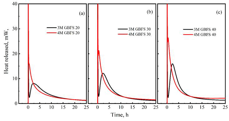
FIG. 1. ICC plots for GGBFS-FA formulations – Effect of molarity and GGBFS content on heat release during ICC at 27°C (a) 20% GGBFS, (b) 30% GGBFS, (c) 40% GGBFS. (binder: NaOH+Na2SiO3 in 1:1 ratio (vol)).
Table 1 presents the Compressive Strength (CS) values of the geopolymer cubes (70 mm) of various formulations with two different binder compositions, 4M and 6M NaOH, at various stages of aging. As seen, formulations with GGBFS content ≥ 20% yielded the targeted strength, 25 MPa; infact the 40% GGBFS formulation achieves the same in 1 day itself if the binder is 1:1 (vol) mix of 6M NaOH+Na2SiO3. The increased CS with the GBFS content can be ascribed to increasing the Si in the polymeric chain (Si/Al) from the amorphous phase rich in Ca and Si. C-S-H/C-A-S-H gel formed in presence of GGBFS also aids strength development. The enhanced CS at higher molarity is due to the increased hydration (as observed in Figure 1) corresponding to the increased Na2O/SiO2 ratio of the binder.
| Binder (1:1 by volume) | GGBF, % | Compressive strength (MPa) after curing for | ||
| 1 d | 7d | 28 d | ||
| 4M NaOH+Na2SiO3 | 20 | 7.21 | 26.76 | 35.03 |
| 30 | 20.1 | 39.38 | 56.46 | |
| 40 | 26.1 | 44.89 | 50.52 | |
| 6M NaOH+Na2SiO3 | 20 | 8.67 | 31.01 | 44.9 |
| 30 | 18.42 | 47.12 | 55.1 | |
| 40 | 27.96 | 51.54 | 66.83 | |
TABLE 1. CS values of geopolymer formulations with varying GGBFS content#.
Porosity changes
Besides strength characteristics, pore characteristics are very much relevant to the efficacy of wasteforms, viz. restricting the transport of ions through porous matrix such as geopolymer/cement; hence this section details the pore size distribution obtained from Mercury Intrusion Porosimetry (MIP) for selected samples (28 day cured) having different slag content.
Figure 2 describes the pore details of the GGBFS-FA formulations (GGBFS: 10, 20, and 30%) with 4M NaOH and Na2SiO3 solutions in a 1:1 ratio (by volume) as a function of pore diameter. The cumulative pore volume (Figure 2a) decreases with an increase in GGBFS content. The pores are in the nanometer range. Figure 2b shows the pore size distribution for these samples.
The modes for all these are below 100 nm. For the 20% GGBFS samples, the mode shifts towards the finer pores compared to that of 10% GGBFS, and the fraction becomes reduced. Though the mode of 30% GGBFS remains more or less at the same position as that of 10% GGBFS, it is much smaller. Being similar, pore size distributions of samples prepared with 6M NaOH and Na2SiO3 solutions are not presented here, but are characterized by smaller pore sizes. The changes in pore characteristics match very well with the strength development features observed in the earlier section. Ismail et al. observed a less dense binding phase at higher FA. The geopolymer gel in FA is less space-filling than the C-A-S-H gel from slag activation. The enhanced pore-filling ability of the C-A-S-H gel (having significant bound water) from GGBFS activation compared to the N-A-S-H gel (low bound water) from fly ash geopolymerization [8] is reducing the porosity of the system as GGBFS content increases; the authors see the effect from low GGBFS addition itself than reported by Provis et al. X-ray tomographic studies reveal gradual reduction of porosity as well over extended periods of time [9].
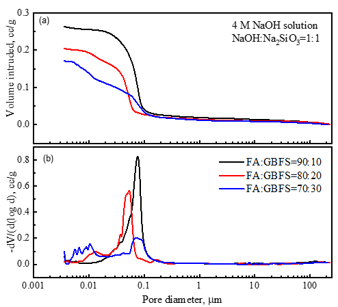
FIG. 2. Pore characteristics of FA-GGFBS formulations (binder: 1:1 mix of 4M NaOH: Na2SiO3 (vol.) (a) cumulative pore size, (b) pore size distribution.
Hydraulic conductivity
The transport properties control the effectiveness of containment; the permeability, a measure of fluid transport, is the most important among many factors. Hydraulic conductivity values indicate how easily pore fluid escapes from the compacted pore space or the chances of escape of encapsulated element. It is one of the principal waste form test protocols. Low hydraulic conductivity to minimize groundwater flow through the embedding substance. Hydraulic conductivity measurements used cylindrical blocks (100 mm diameter) with 4M NaOH+Na2SiO3 (1:1) and 6M NaOH+Na2SiO3 (1:1) binder solutions for formulations 70:30 and 60:40 (FA: GGBFS).
Hydraulic conductivity values, measured as per BS1377 P-6 protocol (Table 2), show the values are of the order 10-10 m/s, the desired range for immobilization. The US Environmental Protection Agency (EPA) guidance for hydraulic barriers recommends an average hydraulic conductivity of 10-9 m/s [6]. Table 2 shows the hydraulic conductivity value for 6M is one order lower; an increase in slag content also decreases the hydraulic conductivity. The changes in values with molarity and slag content follow the changes in porosity (and tortuosity) discussed earlier.
| Molarity | FA:GGBFS | Dry density, (g/cc) | HC, × 10-10 m/s |
| 6M | 70:30:00 | 1.68 | 0.1868 |
| 4M | 70:30:00 | 1.64 | 1.544 |
| 4M | 60:40:00 | 1.73 | 1.109 |
TABLE 2. Hydraulic conductivity values different formulations.
Leaching studies
Leaching of the constituent elements from geopolymer samples described in our earlier publication [10] in distilled water reveals that the order of leaching rate, irrespective of the formulation, is Na (10-4)>Si (10-5)>Al (10-6)>Fe (10-7). Relatively high leaching rate observed for Na and Si are from unreacted/excess NaOH ans Si atoms that are not part of the geopolymer network. Absence of Ca in the leachate from the geopolymer matrix, unlike in the case of cement based matrix, illustrates the superiority of the developed geopolymer matrix vis-à-vis over concrete barrier adopted for immobilization of low and intermediate level radioactive wastes. Water immersion of the blocks has slightly enhanced the CS values. A separate study measured the leach rate of 137Cs from the formulations of geopolymer and Ordinary Portland Cement (OPC) prepared with 137Cs tracer radioactivity has shown that Cs release (leach rate) from geopolymer matrix is lower by an order vis-à-vis OPC based matrix; to restricts the Cs release, OPC-based barriers need to be complemented with vermiculite.
Scale up studies
Characterization of the geopolymer matrix described above show that geopolymer matrix has the required characteristics in terms of the strength, porosity, durability, leaching etc. We have confirmed that the raw materials variation does not much effect on the strength characteristic. Above results reveal that the FA+GGBFS geopolymer charcteristics (compressive strength, porosity, hydraulic conductivity, leaching behaviour, etc.) conform to the requirements of radioactive waste immobilization for GGBFS content >20%; hence, scale up studies used formulations with GGBFS content 30 and 40%.
5 kg geopolymer blocks:
The first step of upscaling is casting 5 kg (GGBFS+FA) of geopolymer paste in a single cylindrical mold. For the 5 kg casts, fly ash and GBFS are from Tata Power Fly Ash and SAIL, Bhilai, respectively. The binder used is a 1:1 mix of NaOH (4M) and Na2SiO3 solution; the reagents used are of laboratory grade, as in the case of 70 mm blocks. The 5 kg material (FA and ground GBFS) vigorously mixed with the binder solution (prepared a day ago) for about 12 min to get the desired consistency. The geopolymer paste is cast in a cylindrical mold (173 mm dia) kept on a vibrating table (size 1 × 1 m), vibrating at a frequency of 60 Hz@ 1 mm amplitude; the mix is slowly added to the mold under vibration for 10 min (total). The cast sample is demolded after curing in the mold for a day (Figure 3). The dimension of the cast is approximately 173 mm (dia) × 171 mm (height). The sample, wrapped in polythene cover is kept for 28 days at around 27°C for curing.
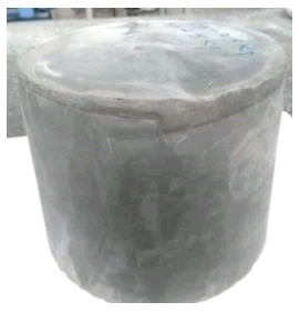
FIG. 3. Typical 5 kg cast in 173 mm diameter barrel.
The blocks were strong enough to drill out core samples from them. A typical 75 mm (diameter) core drilled out from the 5 kg block (Figure 4) shows a smooth surface, indicating its robustness.
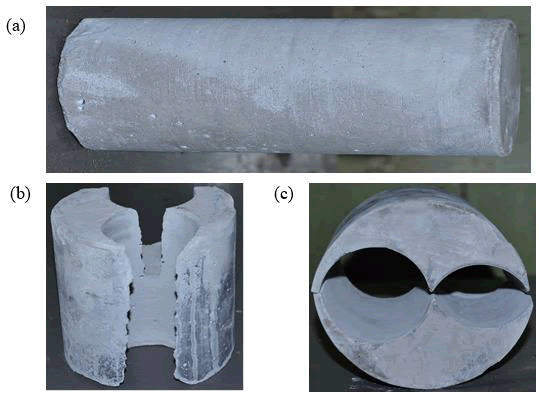
FIG. 4. Core drilling of 5 kg samplers (a) drilled core, (b) and (c) portion after drilling.
To understand the permeability, the authors adopted a more practical approach, the depth of penetration of water under pressure. It tells the uniformity of the structure and zones of deterioration, if any. The depth of penetration of water under pressure (for the 5 kg blocks) were according to Indian standard [11] for hardened concrete. This method involves subjecting the test specimen of the 28 days cured geopolymer cast under pressure 500 ± 50 kPa for 72 ± 2 h after water saturating the blocks as per the procedure. Once the test is over, the block is split in a plane perpendicular to the face on which water pressure was applied. Water penetration front and the maximum penetration (for acceptable water penetration fronts) gives an idea of the permeabilty.
Depth of penetration under pressure tests of FA: GGBFS=70:30 and FA:GGBFS=60:40 formulations with an alkaline binder (4M NaOH+Na2SiO3 in 1:1 ratio by volume) showed that both of them had acceptable penetration front/curve, concave in nature. The maximum depth of penetration for the formulation FA:GGBFS=70:30 was 48 mm while that for the FA:GGBFS=60:40 was 28 mm; the maximum penetrations are within the permissible limit of 50 mm. So, the blocks pass the permeability tests. Significantly low values for the 60:40 formulations (compared to the 70:30 formulation) is in agreement with their porosity; larger amount of pore filling geopolymer gel with larger GBFS content makes this happen [12].
Scaling up to 100 kg blocks
This section describes upscaling the process further to prepare 100 kg geopolymer blocks. The FA: GGBFS formulations chosen for the 100 kg blocks, based on the studies at 70 mm cubic samples and 5 kg of geopolymer casts in a single cylindrical mold (173 cm diameter) in the previous section, are 70:30 and 60:40.
100 kg block preparation:
For the 100 kg casts, the fly ash and GGBFS used for 100 kg blocks are from Tata Power (Jojobera) and Tata Steel (Jamshedpur), respectively. The binder used is a 1:1 mix of NaOH (4M/6M) and Na2SiO3 solution; unlike in studies up to 5 kg, industrial-grade reagents are used for 100 kg studies to simulate a real immobilization.
The process involved dry mixing of the FA and GGBFS in a Pan mixer (Figure 5 and Table 3) for 5 minutes. Thereafter, the binder solution, NaOH solution (6M/4M), and Na2SiO3 solution in 1:1 ratio by volume, prepared a day before was added and continued mixing for 7-9 min. After the requisite mixing, the paste was slowly transferred to the mold, which was kept on a vibrating table (Figure 6 and Table 4). Continued the vibration for 10 minutes after the complete transfer of the paste to remove the entrained air to the extent possible.
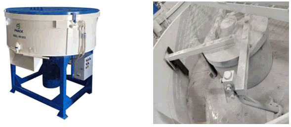
FIG. 5. Pan mixer used to mix 100 kg of FA-GBFS powder and binder solution.
| Particulars | Description |
| Type | Pan mixer |
| Dimensions | 900 × 500 mm (diameter × height) |
| Gearbox | Motorized, 3 HP 1440 RPM, reduction ratio: 40:1 |
| Mixing arms | 4 No. |
| Make | Pledge International, Ahmedabad, India |
TABLE 3. Details of the pan mixer used.
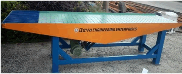
FIG. 6. Vibration table used for 100 kg block compaction.
| Particulars | Description |
| Type | Linear Motion type vibrating table |
| Dimensions | 2500 × 500 × 950 mm (length × breadth × height) |
| Motor | 2 HP Bottom-mounted unbalanced motor 2800 RPM, amplitude of vibration: 1-2 mm |
| Capacity | 150-200 kg |
| Make | Reva Engineering Enterprises, Loni, Ghaziabad - 201102, India |
TABLE 4. Details of the vibrating table used.
Challenges faced during 100 kg block preparation: The typical binder/reactant ratio used for studies up to 5 kg blocks is ~ 0.35. The authors attempted to repeat the same binder/reactant ratio for 60:40 (6M) formulations at 100 kg as well. The trial failed because of the poor workability and the paste solidified during transfer to the mold. Consolidation of such a mix, especially of geopolymer, in large quantities (~100 kg) in a single block is quite impossible due to (1) Low solid/liquid ratio, (2) High viscosity chemicals (alkali hydroxide and silicates), (3) Presence of fast-setting GBFS, etc. Authors have not come across any literature on the preparation of such a large geopolymer cast.
The remedial measures to minimize the issues may include: (1) The quick transfer of the charge mix to the mold on a high frequency/intensity vibration table, (2) The use of a needle vibrator during charging and compaction on a vibration table, (3) The use of more binder solution, and (4) The use of viscosity modifiers such as superplasticizers [13]. The first two options do not alter the chemistry but need to see their effectiveness. Increasing the binder volume may result in excess binders (and issues associated with that and cost) together with increased porosity; Patankar et al. and Xie et al. report a decrease in the compressive strength, perhaps due to the increased porosity. Superplasticizers (polycarboxylates or lignosulphonates) in general ensure easy mixing and compaction, but with a slight CS reduction; of course, the effectiveness may depend on many factors such as the nature of the activator, etc. [14].
The authors adopted a two-pronged approach, the usage of a superplasticizer during mixing and the use of a needle vibrator during the transfer of the paste to the mold (on the vibration table) and vibration. The superplasticizers used in the trials were Sika 2004 (lignosulfonate-based) and Optima K15 (polycarboxylate-based); they were added after the addition of the binder solutions. The authors have ensured, by repeating the tests described in earlier section with these plasticizers, that the superplasticizers are not affecting the compressive strength seriously. After the requisite mixing in the pan mixer, the paste was transferred to the mold, which was placed on a vibrating table (about 5 kg at a time). Besides the vibration using the vibration table, a needle vibrator was also used to enhance the compaction.
Our experiments (without any superplasticizers, but with a needle vibrator) have shown that good mixing requires a binder-to reactant ratio of 0.37 or more; as a result, there was no problem in 100 kg geopolymer blocks. The ambient temperature also has a role; increased temperature makes the mixing easier. Mo (as 0.1M Mo solution) addition of 0.1% has not affected the mixing. Figure 7 presents a typical sequence of 100 kg block preparation while Figure 8 depicts typical 100 kg clocks prepared.
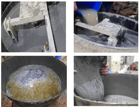
FIG. 7. Different stages of 100 kg geopolymer preparation, (Clockwise from top left): Dry mixing, binder addition, transfer to the mold, and vibration.
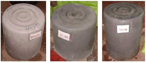
FIG. 8. Geopolymer casts at 100 kg scale.
Polycarboxylate-based and sulphonate-based superplasticizers improved the workability and mixing. The addition of 0.5% superplasticizers has improved the ease of transfer and mixing to have a hassle-free casting even for the binder-to-reactants ratio of 0.35 but at higher ambient temperature (>35°C). Experiments with 1.5% Sika 2004 NS have proved that even at low ambient temperature (27°C), hassle-free transfer, mixing, and casting (100 kg blocks) is possible even with a binder to reactants ratio of 0.35%.
Property evaluation of 100 kg blocks:
Compressive strength and hydraulic conductivities are the target properties. The property evaluation is from the properties of cores drawn from these blocks (from the center and other locations of these blocks). Blocks were drawn from these blocks using a core drilling machine (Figure 9) for hydraulic conductivity analysis and compressive strength measurements. Core drilling of samples from the plasticizer-added block was easy and drilled out in one shot, whereas the core drilled from the other one broke in the middle. The hydraulic conductivity measurements of the samples were done based on the BS1377 P6 procedure while that of the compressive strength was based on IS 9143 1979 RA 2016.
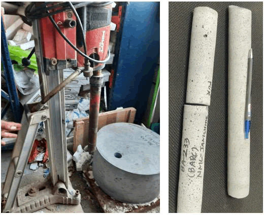
FIG. 9. (Left) Core drilling of 100 kg samples, (Right) Drilled out cores.
Compressive strength evaluation: Table 5 lists the compressive strength values of cylindrical cores drilled from the 100 kg geopolymer blocks (as per IS 9143 1979 RA 2016 procedure) along with sample dimensions and density. All the values can be seen to be above 20 MPa; but, the cube equivalent strength is 1.25 times higher, and matches the target strength of 25 MPa. However, it is less than the corresponding values obtained with small samples (70 mm cubes). One main reason is the strain accumulated in the structure during transportation in a commercial vehicle to the core drilling lab located around 1000 km and that developed during the drilling of the cores. A better vibration system may also be tried to enhance the compaction.
The samples prepared with the addition of plasticizer (BA233) are seen to have reduced strength compared to those without it (BA279). A close look at the density values indicates that the compaction in plasticizer-added blocks is similar, if not worse, to that without a plasticizer despite the enhanced mixing. It is to be seen whether the added plasticizer is responsible for their inferior strength. Besides, the applicability of plasticizers for the intended application is also to be explored. The CS values of core samples drilled across the diameter (1, 2, and 3) are similar (for both plasticizers added and without that) showing uniform compaction across the cross-section.
| Sample | FA:GGBFS, Molarity | Sample dimension, cm | Density, g/cc | CS*, MPa | ||
| Length | Diameter | Dry | Saturated | |||
| BA233-1 | 60:40, 6M | 8.621 | 4.324 | 1.54 | 1.81 | 20 |
| BA233-2 | 60:40, 6M | 8.57 | 4.244 | 1.52 | 1.76 | 21.5 |
| BA233-3 | 60:40, 6M | 8.638 | 4.36 | 1.43 | 1.82 | 18.5 |
| BA279-1 | 60:40, 6M | 8.697 | 4.307 | 1.62 | 1.84 | 27 |
| BA279-2 | 60:40, 6M | 8.721 | 4.418 | 1.67 | 1.9 | 27.4 |
| BA279-3 | 60:40, 6M | 8.718 | 4.416 | 1.62 | 1.86 | 26.9 |
| Note: *measurement on saturated samples, BA233 with 1.5% Sika2004NS | ||||||
TABLE 5. Compressive strength values of cores drilled from 100 kg blocks.
Hydraulic conductivity: The procedure used for hydraulic conductivity values of cores drilled from different locations was as per BS1377 P-6 protocol. The hydraulic conductivity values are, be it from the plasticizer-added geopolymer block or that made without plasticizer addition, are of the order 10-10 m/s, which is in the desired range. However, the values show lower hydraulic conductivity for the plasticizer-added blocks, perhaps due to better packing and compaction. Though the conductivity is of the same order, the hydraulic conductivity showed a continuous decrease from the rim (3.095 × 10⁻¹⁰ m/s) to the centre (2.5 × 10⁻¹⁰ m/s) for the geopolymer block without plasticizer. Such a difference is not noticed for the plasticizer added block (variation: 2.1 × 10⁻¹⁰ m/s to 2.4 × 10⁻¹⁰ m/s). Strains of various types developed in the structure during transportation and core drilling might have adversely affected the hydraulic conductivity values as in the case of compressive strength values.
L/D variation: L/D studies used cylindrical molds of the same diameter but used different weights of geopolymer paste to have different L/D. Geopolymer pastes of 25 kg, 50 kg, 75 kg, and 100 kg (made from FA, GBFS, and binders), were cast in four cylindrical molds on the same day. Table 6 lists the changes in compressive strength values with increasing L/D using cores drilled from these blocks. The CS values do not show any significant variation with an increase in L/D.
| Sample Id | Wt. solid, kg | L/D | Temp, °C | Binder Solution (NaOH+Na2SiO3) | CS, MPa | ||
| Solution proportion | NaOH molarity | Solution, % | |||||
| BA296 | 25 | 0.17 | 28 | 1:01 | 6M | 40 | 32.71 |
| BA297 | 50 | 0.34 | 28 | 1:01 | 6M | 40 | 25.16 |
| BA298 | 75 | 0.51 | 30 | 1:01 | 6M | 40 | 30.35 |
| BA299 | 100 | 0,62 | 30 | 1:01 | 6M | 40 | 30.1 |
| Note: FA-Tata Power, Jojobera, GGBFS-Tata Steel Jamshedpur, very good mixing | |||||||
TABLE 6. Details of L/D variation studies of geopolymers.
Way ahead
For the utilization of nuclear waste streams in geopolymers for immobilization of radionuclides, the incorporation of plasticizers presents significant challenges because nuclear waste streams are typically multielemental in nature and contain high Total Dissolved Solids (TDS) as well as high total solids content. These characteristics influence rheology, workability, and homogeneity of the geopolymer matrix.
Achieving molecular-level homogeneity or effective micromixing is critical for ensuring uniform radionuclide immobilization. Equipment selection is constrained by the highly viscous and heterogeneous nature of such formulations. High-speed mixing (or high-shear mixing) is an option that improves the rheology without altering the chemistry (avoiding the usage of chemical admixers) of fresh cementatious pastes; during high speed mixing ensures better dispersion of particles by breaking the flocculated structure of particles. But, care has to be taken to ensure that the mixing intensity be within the threshold, besides possibility of accelerated initial hydration owing to the increased exposed surface area in the deflocculated system.
In this context, we have tested mixing in one such mixer, viz. sigma blender, suitable for viscous systems; it contains a stationary horizontally trough in which two sigma shaped blades (fitted at a close, specified clearance with the mixing chamber to ensure thorough and uniform mixing) rotate in inward opposite direction. The mixing mechanism combines bulk movement, shearing, stretching, folding, dividing, and recombining actions.
The mixing action causes generation of fresh interfacial surfaces, allowing enhanced component interaction and dispersion. The kneading phenomenon, which is intrinsic to this design, promotes intricate and homogeneous mixing suitable for high-viscosity geopolymer systems.
In our initial tests, the observed mixing of geopolymer formulations in sigma blenders are advatageous. Our tests with FA and GGBFS (60:40 by weight) and the binder solution (6M NaOH solution and Na2SiO3 solution in 1:1 ratio by volume) with solid: liquid=0.4 yielded a well pourable product.
Further, the blender aims to provide solution to multiple waste streams groutingas geopolymerised product.
Conclusion
Following are the salient features of this study towards developing a geopolymer matrix suitable for immobilizion of the radioactive nucleoids in the waste:
• Fly ash (FA)-Ground Granulated Blast Furnace Slag (GGBFS) based geopolmers (GGBFS>20%) satisfies the required properties
• Increase in GGBFS content increases the CS while the porosity and hydraulic conductivity decreases.
• Casting of the viscous geopolymer mix is a tricky; the authors cast the mix on high frequency vibrating table together with a needle vibrator to have proper consolidation and prevent setting during transfer in the first phase. Use of plasticizers makes the mixing, transfer, and consolidation easy.
• Utilisation of high shear sigma blender in the second phase made the need of plasticizers redundant.
• Characterization of the drilled core samples show that the large blocks also satisfies the CS criteria.
Acknowledgment
The authors acknowledgment the encouragement and infrastructure support provided by Smt. Smitha Manohor, Dr. CP Kaushik and Shri U Dani from Bhabha Atomic Research Centre. The authors are thankful to the CSIR-NML and BARC managements for their permission to publish the findings. The CSIR-NML authors acknowledge BARC for funding they received for the work (SSP 1252).
Author Contribution
Dr. TC Alex (tc_alex@yahoo.com) and corresponding author have made equal contribution in this work.
References
- Ambashta RD, Alex TC, Singla R, et al. Evaluation of different fly ash-blast furnace slag formulations for design of geopolymers in radioactivity disposal applications. Trans Indian Ceram Soc. 2024;83(3):178-187.
- Casas AL, Goulart de Araujo L, Vicente R, et al. Toward sustainable radioactive waste management: Geopolymerization of sewage sludge ash as a viable solution. ACS Omega. 2025;10:7683-7696.
[Crossref] [Google Scholar] [PubMed]
- Fisher M. IAEA bulletin. 2020;61(3).
- Ismail I, Bernal SA, Provis JL, et al. Modification of phase evolution in alkali-activated blast furnace slag by the incorporation of fly ash. Cem Concr Compos. 2014;45:125-135.
- IAEA-TECDOC-972. Technologies for in situ immobilization and isolation of radioactive wastes at disposal and contaminated sites, ISSN 1011-4289, IAEA, Vienna, 1997.
- Liu J, Xu Y, Zhang W, et al. Solidification performance and mechanism of typical radioactive nuclear waste by geopolymers and geopolymer ceramics: A review. Prog Nucl Energy. 2024;169:105106
- Lichvar P, Rozloznik M, Sekely S. Behaviour of aluminosilicate inorganic matrix sial during and after solidification of radioactive sludge and radioactive spent resins and their mixtures. IAEA Report INIS RN 44122421. 2013.
- Jawerth N. What is the clean energy transition and how does nuclear power fit in? IAEA Bulletin. 2020;61(3).
- Jithendra C, Elavenil S. Role of superplasticizer on GGBS based geopolymer concrete under ambient curing. Mater Today Proc. 2019;18:48-154.
- Nematollahi B, Sanjayan J. Effect of different superplasticizers and activator combinations on workability and strength of fly ash based geopolymer. Mater Des. 2014;57:667-672.
- Patankar SV, Jamkar SS, Ghugal YM. Effect of water-to-geopolymer binder ratio on the production of fly ash based geopolymer concrete. Int J Adv Technol Civ Eng. 2013;2:79-83.
- Provis JL, Myers RJ, White CE, et al. X-ray microtomography shows pore structure and tortuosity in alkali-activated binders. Cem Concr Res. 2012;42:855-864.
- van Jaarsveld JGS, van Deventer JSJ, Lorenzen L. The potential use of geopolymeric materials to immobilise toxic metals: Part I. Theory and applications. Miner Eng. 1997;10:659-669.
- Xie J, Zhao J, Wang J, et al. Impact behaviour of fly ash and slag-based geopolymeric concrete: The effects of recycled aggregate content, water-binder ratio and curing age. Constr Build Mater. 2022;331:127359.