Original Article
, Volume: 15( 4)Designing and Developing Solar Energy Operated Water Pump for Small Scale Irrigation
- *Correspondence:
- Muthiya SJ Department of Automobile Engineering, Hindustan University, India, Tel: 9094411654; E-mail: Jenoris.555@gmail.com
Received Date: July 27, 2017 Accepted Date: September 13, 2017 Published Date: September 18, 2017
Citation:Frenjo A, Wogasso A, Ravi R, et al. Designing and Developing Solar Energy Operated Water Pump for Small Scale Irrigation. Int J Chem Sci. 2017;15(4):194
Abstract
In this paper, a solar energy operated water pump is designed for a small-scale irrigation system replacing the conventional system which makes use of natural fuels that are exhaustible and non-friendly to the environment. The main concentration of implementing solar power source is because of its abundance and it is more volatile than any other fuel resources. The solar powered water pumps can be even implemented in hilly areas where transmission of power from grid is even impossible. The cost involved in solar powered water pumps is very less when compared to conventional systems. A solar water pump is designed and experimented and satisfied results are obtained.
References
Chinese Food Recipes Blog | Thai Food Recipes French Food Recipes Indian Food Recipes Blog | Casino Sites in South Africa Italian Food Recipes Blog | Best Betting Sites in India Japanese Food Recipes Blog - Find Lawyer in Florida Korean Food Recipes Blog | Best Betting Sites in Turkey Mexican Food Recipes Blog | Casino Sites in Argentina Blog | Best Betting Sites in Canada Turkish Food Recipes Blog | Fan Tokens Info Vietnamese Food Recipes Blog | Engine Technologies Articles Yacht Charter in UAE Blog | All About Digital CoinsKeywords
Inc Solar energy operated water pump; Small scale irrigation system; Conventional system
Introduction
The purpose of this project is to construct solar energy operated water pump for small scale irrigation as stated in chapter one. The main contribution of the project is to; reduce the environmental pollution due to the exhausts emissions from conventional water pumps used for small scale irrigation and reducing the foreign currency by reducing the amount of conventional fuel which is imported to operate different mechanical engines including water pumps for irrigation purpose. The conventional water pump has high noise especially if it is diesel engine which affects the wild animals and migrating them from the area. In addition to that the conventional fuel which is used to operate the water pump engine should be transported to the farmer and if leaks on farm land it contaminates the farm affecting the final product. The project location is Methara town where the Kereyu tribes living around the town situated on the geographical location latitude 8.9°N and 39.92°F elevation is 1007 M above sea level. The average temperature of the town is 30.5°C and the wind is blown at a speed of 1.5 m/s to 3 m/s, average humidity of the town is 34.9%, atmospheric pressure 1008.8 pas. This town is cloud around 25%. The area is sandy and due to this reason, the water main canal that the government was made had plastic shield to the ground to prevent the water from sink in to ground. Another feature of the water canal that the design determined is the level of water main canal is lower than the field. As a result, the canals could not supply sufficient water to the farm land and some of them are even clogged [1].
The onion need more water during the sunny day. Onion is widely grown across a range of climate but it is best when temperature is cool during early development and then warmer and sunny during maturation. Onion is recommended to be irrigated for two to three days per week and also when it is irrigated the morning is preferable than at mid-day or the warmer time of the day. Too much water is lost by evaporation if irrigation is done at the warmer day time. The below Figure 1 shows a clogged cannel [2].

Figure 1: Clogged cannel.
In order to avoid such complications and to irrigate the farmlands effectively a solar powered water pump is designed and a schematic representation of the whole plant is shown below in Figure 2.

Figure 2: Schematic of Solar powered water pumping.
Construction of Solar Powered Water Pumping
For solar energy, operated water pump energy design is crucial and front step. Every design is proceeding from energy design. During energy design the researcher study the nature of irrigation, types and different application of solar water pump. Pumping is the hydraulic energy required to deliver a volume of water. This hydraulic energy in joule can be calculated by the following formula:
Where,
E: the hydraulic energy;
Ρ: density of water;
G: gravity of the water;
V: volume of water;
H: head of the pump;
E: ρgVh.
The required energy pumps highly depend on the demand of water and the head of water level. The area at which the solar water pump is constructed is Eastern Showa Methahara Kereyu farm lands as described above. The quantity of water then increased by increasing the water pump horse power and the electrical energy which is controlled by the solar panel and intensity of solar radiation. The researchers selected this area because in that area, hence it gets good sun light rays which is collected by the solar panel and used to charge the storage solar battery and operate the electrical motor that rotates the impeller. During the project implementation, different tasks are performed. The project includes constructing and testing the water pumps for real operation with minimum pump and solar panel used to operate the brushless DC motor. Most of the components of the system are bought from the markets. For this project, the prototype solar energy water pump is constructed and tested. The plantation which is selected for the system is onion and the farm land area is half of a hectare. This project touches many theoretical and practical areas to become real on the ground and to achieve the objectives. The selection of material and methodology is so important and critical to optimize the success. Material selection such as panel, battery and the method to connect the electric panel to battery, battery to DC motor is performed with great care to protect the system from damage and burn. At the same time piping the water from source to farm also considered before going in to work engagement. Since the solar energy is abundantly found in Ethiopia the project is applicable in different areas of Ethiopia in addition to that of area indicated in the project. Parameters that are considered during project implementation to have better pumping efficiency are as follows:
1) The density of water: As the water density increase due to the content of sand and mud, its flow rate is highly affected. The water with more sand and mud it may clog the waterline and pump.
2) Section head: Head height from water to reservoir will determine the power required to pump the water from the ground.
3) Size of field: The size of the land will determine the required water for irrigation which sizing the pump and the tank.
4) Solar radiation: The efficiency of the solar panel is depended on the light intensity arrives on the panel. If more radiation is available on the field the induction of DC current in the solar cell will be more [3].
Materials Used to Construct the Project
There are different materials and components which are used to construct the solar energy operated water pump. These systems and components are well constructed together to produce the final project result. The materials are selected considering the overall cost such as initial cost, running cost and maintenance cost [4-8].
Solar panel (PV)
The solar panel which is selected to perform the project is DC photovoltaic (PV) cells which are made of semi-conducting materials that convert the sun light ray directly to electricity (Figure 3). When sun light strikes the cell, it dislodges and liberates electrons within the material which then move to produce a direct electrical direct current (DC). This direct current then used to charge the solar storage battery and operates the pumping motor. The purpose of photovoltaic panel is to convert the sun light which is abundantly found in to electrical energy. For this project, the size of the PV is 0.56 m2 of three 12 V series connected batteries and 60 w. The ratio of proto type is three to one the area of one PV panel is 0.18 m2.

Figure 3: Photovoltaic (PV) panel.
Sizing of the PV panel determine the electrical energy which is used to charge and operate the pumping motor. If the size of the photovoltaic panel increases the output energy of the overall system sizing also increase and the amount of water which pumped increase determining the area which is irrigated can also be increase. Therefore, the overall selection of the panel depends up on the area of the farm land which is cultivated and the type of seeds. For this project, the above indicated size of the PV panel is selected.
Pumping motor
There are different types of electrical motors which are designed to perform different tasks. The electrical motor which is designed to perform this project is brushless direct current (BLDC) motor (Figure 4). The BLDC motors are one of the electrical motor types rapidly gaining popularity and are used in industries and are found in the market. As the name implies the BLDC motors do not use brush for commutation, instead they are electronically commuted and have many advantages over that of brushed direct current motors such as:

Figure 4: Brushless DC motor.
1) Better speed vs. torque characteristics;
2) High dynamic response;
3) High efficiency;
4) Long operating life;
5) Noiseless operation;
6) Higher speed ranges [9].
In addition, the ratio of torque delivered to the size of the motor is higher, making it useful in applications where space and weight are critical factors.
The type of pumping motor system for this project is surface pumping motor system hence there are also some other types such as submersible pumping systems are also there. The pumping system sizing for the motor is determined by the power required to move the water. So, to select the motor the researchers should determine;
1. How high the water needs to be pumped;
2. How much water is needed per day;
3. How fast the water needs to be pumped, i.e., the nominal flow rate of the pump (per minute or second) and whether it is compatible with the well/spring capability;
4. For solar: Available solar energy (PSH/kWh/m2).
Depending on the above parameters the power of the pump which is selected for the project is BLDC motor having 0.442 Nm with 825 w. Hence the project shows the prototype and testing it for the real project with small value (Figure 5). If other researchers want to construct the project the size of the components should be increased based on the size of the irrigation.

Figure 5: Pumping impeller [9].
Pumping elements
The pumping elements which are known as impellers are components which are used to suck and pressurize the water to move to the expected place in this project reservoir. The type of impeller which is used for this project is centrifugal pumping impeller which is fixed on the brushless dc motor by using some modifications on the electrical motor.
Storage battery
The solar storage battery stores the electrical energy in the form of chemical energy. This chemical energy is then performing electrical tasks when the circuit is completed. For this project, the storage battery which is used is 12 V, 20 Ah and come to operation when there is no sun light or the sun is covered with cloudy and the pumping motor is needed to operate (Figure 6). The most common type of battery found in PV system is the lead acid battery. Therefore, the storage battery that is used is lead acid class of battery, because this type of battery has higher performance characteristics and suitable for air transportation.

Figure 6: Gel storage battery.
Charge controller
The charge controller is the component in the circuit which is used to control the condition of the charging, that is whether the storage battery is fully charged, 50% charged or discharged and controls the panel itself indicating whether the panel is in operation or not (Figure 7).

Figure 7: Solar charge controller.
In addition to this the charge controller monitors the state of charge of the battery bank, the charging process and the connection/disconnection of loads.
The water reservoir
The water reservoir is used to reserve the water which is pumped and after or simultaneously irrigating the farm lands. Whenever the sun light is covered by cloud or there is no sun light, farmers can use the reserved water for irrigation (Figure 8). The elevation at which the reservoir is mounted is higher than the farm land hence the pump is set at off position the water is moved by gravitational difference. The reservoir can be constructed by concert like water tank or one can use the plastic tanks which are installed on stands.

Figure 8: Water reservoir (tank).
Panel frame
The panel frame is designed to hold the PV panel safely. We have one PV panel which is 60 cm × 30 cm. The panel with L shape steel should cut with 2 cm clearance to each side of the panel. The steel is attached with L shape and weld outside of the panel place (Figures 9 and 10). The size of the panel frame is reducing from the real project by the ratio of three to one.

Figure 9: PV Panel frame.

Figure 10: PV Panel with attachment.
Then this holder designed to be supported by circular pipe steel which has 2.5 mm thickness. The steel should weld at the centre of cross attached to the panel holder. Then the cross welded unit weld at half of four frame sides.
The cross welded rectangular steel well attached at the centre of the welded by safely to avoid weld loss and break (Figures 11-14). To have better attachment those welded steel also attached to 2 cm thickness steel.

Figure 11: Sheet metal.

Figure 12: Square pipe.

Figure 13: PV Panel on the position.

Figure 14: Pumping motor seat.
The squared pipe steel which have 40 mm × 40 mm of width attached to the flat steel by outside welding. The squired pipe has 1.50 m height. Out of this length 20 cm of the steel is immersed in to the prepared concrete to have better seat of the PV pole, the other end is welded with the flat steel.
Panel holding units
The PV panel is carried by the metal frame and it secure on the well-built concrete through main supporter.
Pumping motor seat
pump has four holes which allow the bolt that fasten the motor in to the ground. The battery putted safely on the battery case which prepared from L shape steel. The case is allowing 2 mm of clearance to freely remove and place (Figures 15-18).

Figure 15: Battery holder.

Figure 16: Schematic diagram of solar operated water pump system circuit.

Figure 17: Block diagram.

Figure 18: Awash basin flooding.
Solar operated water pump circuit diagrams
The controller has 6 slots for wiring three components:
1. The solar is connected to the controller; both negative and positive cable is connected to the controller.
2. Battery positive and negative terminal also connected to the controller through the battery slots.
3. The load slot is remaining slot which not needed to our project. The overall circuit connection is based on the instruction manual placed.
Circuitry diagram of the system: The schematic diagram below shows that the circuits from solar to the solar operated water pump.
Methods
Before the real project is designed and developed, the researchers travelled to the site area for one day and interview with farmers and agriculture officer for further information. The project team asks brainstormed with the officers and gathers information. From the information lot of hectares of farming land was prepared for farming but due to geographical location some of the land is remaining and living out of planting. The office was provided the pumps to the farmers with long term paid. But due to the fuel cost and frequent maintenance need those farmers stop their cultivation and the land was dry. From observation and questioner, the researcher got there is problem that the farmers have no technically skilled to maintain and even to afford the replace parts. The researchers put the solution that the solar operated water pump is the correct design for such kind of problem. It has less operation costs and no fuel used with equivalent pump efficiency.
Design and calculations of the project system
Water requirement: The first step in designing a solar-powered water pump system is determining the overall water requirement for the operation. The total volume of water which is required for one-hectare onion irrigation is calculated as shown below:
Water requirement/week=total farm area × required Gallons of water for one
Square meter/week (1)
Where,
One hectare=10,000 m2 and one m2 area needs five gallons per week
Water requirement/week=10,000 m2 × 5 gallons/week
Water requirement/week=50,000 gallon/week.
The following schematic diagram shows the procedure of project:
Water source: The water source for the planned project system is Awash basin flooding water. The stream flows year-round with sufficient flow to supply the planned system, and the water quality is suitable for irrigation system. However, adequate screening materials are used at pipe intake (or suction point).
System layout: The researchers are to determine the layout of the proposed project system. Based on the site specific data the researchers are to decide all necessary distances and elevations for the intake (or suction) point pump location, PV panel’s location, water tank place, and water discharge point as follows:
1) Intake (or suction) point=0.5 m in depth
2) pump location=mount on dry surface at 1 m from water surface
3) Water tank place=at the elevation of 3 m from water surface
4) Water discharge point=2 m above the tank bottom
5) PV panel’s location=at a distance of 3 m from battery. This place is good south facing and well suited for solar power.
6) Depth of water source=1.5 m
7) Distance between pump and water tank=6 m
The tank, pump and PV panels can all be located in close proximity to one other in order to minimize electric power and pipeline friction losses.
Water storage tank: The total water storage capacity of the tank is sufficient for a minimum of one week water use. To reduce the cost of the project the researchers select minimum storage capacity water storage tank. Minimum storage capacity is calculated as follow:
Water storage tank=water requirement per week × one week
=189,250 L/week × 1 week
=189,250 L
Solar insolation and PV panel installations on site: Project team investigate the site solar insolation. The investigation conducted by project team on the actual solar insolation at the site. The site gats full day solar energy so that possible to use solar panels as energy production. Our site location is free from any significant shading, so in order to achieve full sun exposure to the panels, adjust the panel to south facing for maximizing the solar-powered system’s energy production.
Most of solar panels installations for water pumps are stationary and oriented due south to take advantage of the maximum sunlight available in the middle of the day. The default tilt angle for a PV panel is equal to the latitude of the location. For a fixed array, this default angle will maximize annual energy production.
A tilt angle of +/-15 degrees from latitude will increase energy production for the winter or summer months, respectively.
• Summer tilt angle=latitude-15° (when the sun is higher in the sky).
• Winter tilt angle=latitude+15° (when the sun is lower in the sky).
Design flow rate for the pump: To calculate the pump flow rate the following two important points are required:
1. Weekly water needs for one-hectare irrigation field is 189, 250 L
2. Number of peak sun hours per day is six (6 hrs)
Change weekly water requirements to daily water requirements.
Daily water requirement=(Weekly water requirements)/(Number of days in a week)
=189, 250/(7 Days)
=27, 035.71 L/day
Because of the pump’s design flow rate is based on the estimated daily water needs for irrigation divided by the number of peak sun hours per day [8], as shown below:
Flow rate(Q)=(Total daily water requirement)/(Total daily solar insolation ×60 min/hr)
=(27,035.71 L/day)/(6 hrs × 60 (min)/hr)
=75.1 L/min
Total dynamic head (TDH) for the pump: To determine the pum’s TDH by using the following equation:
Total dynamic head (m)=Total vertical lift (static head)+HL+friction loss
TDH(m)=Total vertical lift (static head)+HL+friction loss
Where,
Vertical lift: is the difference between the water surface at the intake or suction point and water surface at the delivery point.
Water depth is 1.5 m from deep surface of the water, the distance between pump and suction point is 1 m.
Distance between pump and maximum elevation is 3 m and the tank height is 1.5 m.
Vertical lift=0.5 m+3 m+2 m=5.5 m
Friction loss (HL): it is the loss of the pressure due to the friction of the water as it flows through a pipe. It is determined by four factors:
1. A pipe size (inside diameter)
2. A flow rate
3. A length of a pipe
4. A pipe roughness
By using the Hazen-Williams empirical formula, calculate the head loss that caused by a friction within a pipe.
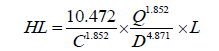
Where,
C: roughness coefficient, when used in the equation it depends on the type of pipe and typically C ~150 [8]
Q: flow rate in gal/min=75.1 L/min
D: nominal diameter of the pipe in meter=0.034 m
L: total equivalent pipe length in meter
Project team selected pipe diameter from pipe manufacturer table of friction head loss for schedule 40 PVC plastic pipe,
C=150.
During a pipe fitting of this project, used the following standard item in the Table 1.
| Pipe fitting | Quantity | L/D |
|---|---|---|
| 90° standard elbow | 4 | 30 |
Table 1. Standard item during a pipe fitting.
The following formula is used for any items during pipe fitting.
Equivalent length (m)=pipe diameter × quantity × L/D
In this project used four 90° standard elbows so that the equivalent length of elbow calculated as follow:
Equivalent length of elbow=0.034 m × 4 × 30
=4.08 m
The total equivalent pipe length in (m)=10 m+4.08 m
L=14.08 m
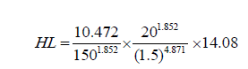
=0.51 m
TDH=5.5 m+0.0001 m+0.51 m=6.01 m.
Pump selection and associated power needed: The pump can be selected by comparing the design flow rate and calculated TDH. The project team select surface (or centrifugal) pump, because this pump is suitable for areas for which the water level is within 7 m below ground level. Surface pump is suitable for pumping from lakes and canals. This selected pump is solar pump that driven by a permanent DC motor which is connected directly to an array of solar panels.
Once a pump is selected, the project team determine at what voltage this pump will operate (12 V, 24 V, etc.,) and how much power (Watts) is required to run this pump by assuming standard pump efficiency (40%). This is the power that de-rated PV modules must supply to operate the pump. De-rating takes into account temperature and soiling effects on the modules. In first step calculate the needed horsepower. Multiply the pumping capacity by the lift, which is the distance that the water must be lifted; then divide the number of daily water requirement (27,035.71).
Hydraulic energy=V × H × ρw × g/(3.6 × 106)
Hydraulic energy (HE)=0.44 Nm
The above calculated newton meter of mechanical work needed to lift a volume of water per unit of time from the pumping water level up to the storage tank can be converted to Watts of electricity by multiplying it by 746.
Watts=0.44 Nm × 746 Watts=330 Watts
In next step that is considered is loss of electricity in the cable and controls during transmission and in converting electricity to the mechanical movements of the pump. The average output rate of these pumps is about 40%. To adjust for this inefficiency, we must recalculate our power input by dividing the value of Watts by 0.40. Minimum electrical efficiency of pumping motor is 330 Watt [3].
Wattage needed=330 Watts ÷ 0. 40=825 Watts.
PV panel selection and array layout: For a solar system, we are chosen the number of solar panels that will produce the number of Watts needed by the pump. Solar panels or modules have different capacities. There are modules of 20, 25, 30, 50, 70 or 75 Watts. It is less expensive to use a more efficient motor than to add an extra solar panel. For our project, we are select less expensive panels that possible to generate the required number of Watts for pump motor. The solar array placed as close to the pump because of minimizing the electric wire length, energy loss and installation costs.
PV array mounting and foundation area: The selected site condition is good for mounting PV panels and site wind speed is less than maximum tolerance. Recommended wind speed tolerance is 85 mph or less. Our site area is located within this recommended wind speed. The site location soil permits the depth of embedment for PV panel’s supports..
Hydraulic workload: Hydraulic work load is calculated by multiplying TDH in unit of meter with daily water requirement in unit of volume. Hydraulic workload is an excellent indication of the power that will be required to meet the system needs. Hydraulic workload (m4)=Daily water volume (m3) × TDH (m)
Daily water requirement=27,035.71 L/day
=27.04 m3
TDH=6.01 m
Hydraulic workload (m4)=27.04 m3 × 6.01 m=162.5 (m4)
Hence the hydraulic workload is less than 1500 (m4); the project is a good for solar PV, if 1500-2000 the system is not complying with the solar system, and if it is greater than 2000 other options then be considered [3].
Results and Discussion
To position the solar panel the researchers conducted a survey study. The position of PV panel determines the output voltage of the solar panel. So, from three recommended position the researcher found 30°south to east. The following voltage reading was recorded during the day time from the solar energy. The record was done from two parts. From solar panel, direct reading and voltage controller (Table 2). The recording is done in one-hour interval for eight hours. The result of the survey is mentioned under the following tables and chart [9-17].
| Time | Voltage | |
|---|---|---|
| Controller(V) | PV panel(V) | |
| 9:30 AM | 1.76 | 9.3 |
| 10:30 AM | 1.72 | 9.6 |
| 11:30 AM | 1.70 | 9.70 |
| 12:30 PM | 1.67 | 10.4 |
| 1:30 PM | 1.65 | 11.0 |
| 2:30 PM | 1.60 | 11.6 |
| 3:30 PM | 1.64 | 10.2 |
| 4:30 PM | 1.65 | 9.7 |
| 5:30 PM | 1.66 | 9.5 |
Table 2. Voltage recording from controller and PV panel.
The above table is plotted on the chart as shown below. It shows the voltage difference from those two parts and the voltage variation based on the time (Figure 19).

Figure 19: Variation of voltage record directly from PV and voltage controller.
Researchers prepared 600 litre water in tank (or container) to check the pumping efficiency of the water pump using the fully charged battery. During the test, the component s of the system are connected as designed on the real site and then circuitry is completed to check the system operation and the flow rate is measured with graduated container. Table 3 below shows the pump flow rate in minute to fill the 20 litre container in one minute. The experiment is done to determine the flow rate of the pump and to conclude the pumping variation while the battery voltage changes.
| Pumping time (sec) | Flow rate (L/10 sec) |
|---|---|
| 10 | 3.33333 |
| 20 | 3.33333 |
| 30 | 3.33333 |
| 40 | 3.33333 |
| 50 | 3.33333 |
| 60 | 3.33333 |
| Total | 19.9999998~20 litre |
Table 3. Pump flow rate using full charged solar battery.
The figure plotted on the chart below show the graphical presentation for the table above. The table placed under this shows the variation of the flow rate due to the voltage drop at battery (Figure 20).

Figure 20: Measuring of flow rate during battery fully charged.
The Table 4 placed under this shows the variation of the flow rate due to the voltage drop at battery (Figure 21).

Figure 21: The variation of flow rate using partially discharged battery.
| Time (sec) | Flow rate (L/7.5 sec) |
|---|---|
| 7.5 | 3.0 |
| 15 | 2.75 |
| 22.5 | 2.6 |
| 30 | 2.5 |
| 37.5 | 2.4 |
| 45 | 2.25 |
| 52.5 | 2.25 |
| 60 | 2.25 |
Table 4. Flow rate of the pump using partially discharged battery.
The pumping efficiency also checked based on varies the head of water source from the pump. The Table 5 below shows pumping efficiency in minute based on the different head position in meter. The test is done using fully charged battery.
| Suction head (m) | Flow rate (L/sec) |
|---|---|
| 1 | 0.33 |
| 2 | 0.30 |
| 3 | 0.27 |
| 4 | 0.22 |
Table 5. Variation of flow rate based on the height of the head.
Here below the Figure 22 show graphical presentation of the flow rate measuring by varies the head (distance between the tank and water source).

Figure 22: Variation of flow rate vs. to head.
From the survey of the PV panel position manual tracking makes PV cells produce constant voltage and during the experiment the sun insolation alone does not influence the voltage. But the position of the PV panel is critical parameter for PV voltage output. The values show that as the PV panel position changed the voltage also varies similar to voltage change while the sun insolation strength varies. The researchers took the record of voltage from two points from those controllers and directly from PV solar panel. The records reflect there is change of voltage from the controller and PV panel. And the value was increased until the mid-day and was decreasing to the time of sunset. Those two hours after mid-day have high radiation at the 30° at 1:30 pm and 2:30 pm. But voltage record from the controller did not change that much and in all recording the voltage is below two volts. The solar pump efficiency is similar throughout the record when the battery is fully charged. And the 20 litre containers could be full in one minute. It shows that the output of the pump is 3.33 litre/sec and it is constant until the voltage is under voltage from the Battery. During slightly discharged battery used for operation of pump the pump output reduced. Especially the first five records the reduction of the flow rate is linear and the last three records are similar. It indicates that as the voltage is reduced from the battery the pumping efficiency of the pump is reduced which mean that the flow rate highly depends on the battery voltage. And also as the head increase the flow rate of water through pump is reduced which mean that the flow rate value is depend on the head of the water source from the pump position.
Conclusion
From the experimental results, the following conclusion has been drawn. The 12 V, 1.11-amp PV panel could give 12 V at 30° south to east. It was found that controller allows the flow of current only if the battery status is low. The 3.33 LPS flow rate of water pump has met the maximum pumping only when the battery is fully charged. As the panel position changed the voltage production at PV panel was found to be changed. According to the experiment as the height increase the flow rate decrease. It is proved that solar water pump is suitable for small scale irrigation.
References
- Awaya H. Autonomous systems in extreme environments (white paper resulting from workshop). Pasadena, CA: Jet Propulsion Laboratory. 1999.
- A report on solar PV applications in India. Published by Centre for Study of Science, Technology and Policy. 2006-2007.
- Tadese A. The unexploited potential improved forages in the mid altitude and low land areas of Ethiopia. Addis Ababa, Ethiopia. 1998.
- Oelert G, Auer F, Pertz K. Economic issues of renewable energy systems. A guide to project planning, GTZ, Eschborn, FR Germany. 1987.
- Design of small photovoltaic (PV) solar-powered water pumps systems. United States Department of Agriculture, technical note No.28, revised. 2012.
- Solar Powered Water Pumping Systems. Technical University, Dresden, Germany and Trakya University, Tekirda? Agriculture Faculty.
- Garg HP. Advances in solar energy technology. Reidel Publishing, Boston, MA. 1987;3.
- Awulachew SB. Water resources investigation and design guideline for potential exploitation in limited data situation: The case of Abaya-Chamo Basin (PhD Dissertation). 2001.
- Helikson HJ, Haman DZ, Baird CD. Pumping water for irrigation using solar energy. Florida Cooperative Extension Service, University of Florida. 1991.
- A Cost and Reliability Comparison Between Solar and Diesel Powered Pumps Solar Electric Light Fund (SELF), 2008.
- Galdabini S, Giuliani G, Robotti N. Photo electricity within classical physics. Proceedings of the Conference on History of Physics in Europe in the 19th and 20th Centuries. 1992.
- Abu-Aligah M. Design of Photovoltaic Water Pumping System and Compare it with Diesel Powered Pump. 2011;5(3):1-5.
- Anonymous. Solar Cells E?E Department of Research on electricity applications, Ankara, Turkey. 1992.
- Amitesai N. Centre for Technology Alternatives for Rural Areas Indian Institute of Technology Bombay Powai, Mumbai. 2012.
- Buschermohle MJ, Burns RT. Solar-powered livestock watering systems. U.S. Department of Agriculture, Machinery Department. Trakia J Sci. 1914.
- Jenkins T. A Solar Choice for Pumping Water In New Mexico For Livestock And Agriculture, New Mexico State University?s (NMSU) Department of Engineering.
- Design of Small Photovoltaic (PV) Solar Powered Water Pump Systems. 2010.
