Original Article
, Volume: 16( 3) DOI: 10.21767/0972-768X.1000277Desalination Aspects of PSSA-g-PEG Copolymer and its Graphene Composite Membranes
- *Correspondence:
- Huda S Kandeel , Chemistry Department, Faculty of Science (Girls Branch), Al-Azhar University, Cairo, Egypt, Tel: +20-1027227142, E-mail: Hudamoon_118@yahoo.com
Received: July 13, 2018; Accepted: July 26, 2018; Published: July 31, 2018
Citation: Kandeel HS, Badawya NA, Hamadaa AA, et al. Desalination Aspects of PSSA-g-PEG Copolymer and Its Graphene Composite Membranes. Int J Chem Sci. 2018;16(3):277
Abstract
In this study, polystyrene sulfonic acid (PSSA) was copolymerized with 1% polyethylene glycol (PEG 600), then Graphene (G) was added at different individually percent of 0.1, 0.5 and 1%, respectively. The resultant membrane designated as (PSSA-g-PEG)/G and was characterized using FTIR, SEM, XRD and TGA analysis. Then, membrane efficiency was determined by measuring the salt rejection and the water flux measured under different parameters such as temperature, pressure and composites concentrations. We found that, increasing temperature and pressure increased membrane water flux, but increasing G portion slightly increased water flux except before and at concentration 0.5% where increasing water flux was growing.
Keywords
Water treatment; Hybrid membrane; Polystyrene; Graphene; Salt rejection
Introduction
Membrane separators are promising alternatives in recent times, due to their high efficiency and applicability in various fields. For example, membranes are currently widely used in water treatment and in reverse osmosis desalination plants but are used on a small scale in the ultrafiltration membrane filters [1]. On the other hand, the solar powered small-scale ultrafiltration membrane systems are currently being used in remote areas which are difficult to drinking safe water, or in natural disasters or in the emergency situations. Key considerations must be taken during development the new membranes, include the cost and scalability, high chemical/thermal stability, high selectivity and high permeability [2]. The membrane must also be designed to separate multicomponent mixtures, resist fouling and have excellent mechanical and chemical stability [3].
Polymeric membranes were found to fail with time due to fouling and chemical degradation, so it was an urgent necessity to develop pure membranes to overcome these drawbacks. It was found that adding inorganic fillers into polymers prevent organization of polymer itself and improve its selectivity performance and increase water flux in the field of water treatment. Polystyrene is a cross-linked hollow fiber backbone and it was turned to a negatively charged polymer when be sulfonated. Rigidity of polystyrene diminishes the chance for the membrane formation [4]. Polystyrene sulfonic acid (PSSA) is a negatively charged polymer can be modulated by adding a water soluble-substance as polyethylene glycol (PEG). Polyethylene glycol was cross-linked with PSSA to increase the hydrophilicity of PSSA [5]. Kim and Lee studied the properties of the PEG molecular weight and concentration on the morphology and water permeation properties of polysulfone/N-methyl-2-pyrrolidone (NMP)/PEG membranes linked with the changes in the thermodynamic and kinetic properties in the phase-inversion process [6]. Xu and Alsalhy synthesized poly (ether sulfone) hollow-fiber membranes with PEG with various molecular weights (PEG-200, PEG-600, PEG-2000, PEG-6000 and PEG-10000) and PVP-40000 as additives and NMP as the preparing solvent. The pure water permeation fluxes enhanced by changing PEG molecular weight from 200 to 10,000 in the dope solution [7].
Incorporation of various nano fillers into polymer matrices like graphene is known to affect membrane structure and properties. Graphene plays an important role in developing conventional polymeric membranes according that it has promising mechanical strength, little thickness and bearing pressure. The major investigations proved that the membrane surface hydrophilicity is influenced by combining nanomaterials that are partially adsorbed on the surface. For example, Mahmoud et al. studied graphene structure, mechanical strength and different properties. He applied graphene sheets in desalination and evaluated the membranes [8]. Arby studied graphene platelets and hybridized it with multi wall carbon nanotubes as a 2 or 3 phase composites in polymer matrix [9]. This paper aimed to study the particular characteristics of PSSA-g-PEG and PSSA-g-PEG\G membranes according to FTIR, XRD, TGA and SEM analysis. Furthermore, studying the performance of these membranes in desalination depending on salt rejection and water flux efficiencies.
Experimental
Materials
Polystyrene waste, polystyrene monomer, Glacial acetic acid (1:2) and Poly ethylene glycol 600 were purchased from Sigma Aldrich, H2SO4 purchased from Honey well company USA and Graphene as nano-composite purchased from Rexipro-German Company. Dichloromethane, methanol as solvent and de-ionized water for washing are analytical grade. Glass plate and DC motor were used with casting knife setting at casting knife gap of 152 μm (6 mils) for membrane fabrication.
Preparation of Polystyrene Sulphonic Acid (PSSA)
In 250 ml bottomed round flask equipped with condenser, 20 g of polystyrene (34% polystyrene monomer: 66% polystyrene waste) was dissolved in 50 ml choloro-methane and stirred for 30 min at 25°C. Then, stoichiometric amounts of H2SO4/Glacial acetic acid (1:2) were added to the styrene mixture, stirred at 400 rpm and fluxed at 80°C for 4 hours to obtain the desired percentage of sulfonation. After that the above solution was slowly poured into ice water and wisely adding methanol to precipitate the polystyrene sulphonic acid (PSSA) as a fine powder. The mixture was then filtered under vacuum and the precipitate was washed three times with 100 ml of methanol as well as de-ionized water and dried in a glass vial under vacuum overnight. To overcome, the agglomerated that tack place during the drying process, the dried polystyrene sulphonic acid was gently crushed in a porcelain mortar. The schematic reaction equation was given in FIG. 1.

FIG. 1. Sulfonation of polystyrene.
Preparation of PSSA-g-PEG copolymer
The castings solutions were prepared by dissolving 10 g of polystyrene sulfonic acid (PSSA) in 50 ml dichloromethane and stirred for several hours at room temperature. Then, polyethylene glycol (PEG 600) was added at percentage of 1, 2, 3, 4 and 5%, respectively, with continuous stirring at 80°C for 6 hours until the solution dissolved completely and became homogenous. The resultant polymer solution was kept in a glass bottle and storage at room temperature to reduce the air bubbles in the casting solution. The prepared polymers were designated as (PSSA-g-PEG) and the polymerization reaction equation was given in FIG. 2.

FIG. 2. copolymerization of PSSA and PEG.
Preparation of PSSA-g-PEG/G
The castings solutions were prepared by dissolving 10 gm of polystyrene sulfonic acid (PSSA) in 50 ml di-chloromethane with stirring for several hours at room temperature. Then, 1% polyethylene glycol (PEG 600) was added followed by adding graphene composites at different individually percent of 0.1, 0.5 and 1%, respectively, then stirring to 6 hours at 80°C until the solution be completely dissolved and homogeneous. The resultant polymer solution was kept in a glass bottle and storage at room temperature to reduce the air bubbles in the casting solution. The obtained membrane is considered one of carbon allotropes composites membrane and designated as (PSSA-g-PEG)/G, finally, the effect of the additives was investigated by preparing the various casting solutions.
Fabrication of PSSA-g-PEG and their composites membranes
The PSSA-g-PEG casting solutions was poured onto a texlan fabric laid flat on a clean glass plate at room temperature. Such solution was placed and spreading on a glass plate using a molding knife with a wet membrane thickness gap specified at 152 μm (6 mL. Immediately after casting, the glass plate with the casted film was dipped into distilled water at room temperature. A membrane casting speed was controlled by a D.C. motor set at 0.10 m/s (20 ft/min) and the film thickness was adjusted 6 mm by means of two integrated micrometric screws. Thereby, after a few minutes a thin polymeric membrane supported on the texlan was then separated out from the glass. All membranes were washed with distilled water and kept in the water bath, to be ready for evaluation. Finally, all the flat membranes sheets were visually inspected for defects and good areas were chosen for membrane evaluation. The fabricated membranes are shown in FIG. 3.

FIG. 3. Facial images of the prepared membranes (a) PSSA-g-PEG (b) PSSA-g-PEG\0.5%G (C) Image shows the elasticity of PSSA-g-PEG\0.5%G.
Characterizations of the prepared membrane
The resultant membrane designated as (PSSA-g-PEG)/G and was characterized using FTIR, SEM, XRD and TGA analysis.
Evaluation of prepared membranes
The efficiency PSSA-g-PEG/G membrane was determined by measuring the ability of removing salts from water (Salt Rejection) and by measuring the Water Flux (membrane water permeability).
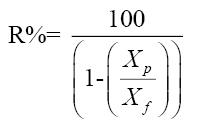
Salt rejection: The salt rejection (R) or the solute separation from the membrane can be calculated from the following equation:
 (1)
(1)
Where Xp and X are the salt concentrations in the permeation and feed streams, respectively. For this reason, two types of saline waters having different saline %, were used, 1) Groundwater specimen having a salinity of 60,000 ppm NaCl, 2) Brackish water containing of 15000 ppm NaCl [10].
Water flux calculations: The pure water permeability, also known as the pure water flux is defined as the volume of water that passes through a membrane per unit time, per unit area and pre-unit of transmembrane pressure. The performance of the PSSA-g-PEG/G membrane was investigated by measuring permeate fluxes and salt rejection capability through passing 2000 ppm of NaCl solutions into the membranes at 225 psi. Thereby, the membrane sample area of 2.212 × 10⁻³ m2, was placed in the test cell with the active skin layer facing the incoming feed. Then the feed water was adjusted at pH between 6- 7 at 25°C and at 1 gallon/minute feed rate. All the water flux and salt rejection were measured after 30 min to ensure that the steady-state operation had been reached.
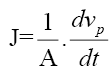
The water flux (J) of PSSA-g-PEG/G membrane was calculated from the equation (2) [4];
 (2)
(2)
Where J is the water flux (L/m2 h), A is the membrane area (m2), Vp is the permeate volume (L) and t is the treatment time (h). From equations 1 and 2, both of salt rejections and water permeate flux versus time were calculated for the PSSA-g- PEG/G membrane. The efficiency of the PSSA-g-PEG/G membrane was selected for the membrane which showed high water flux percentage. Also, the effect of pressure and temperature was applied to this membrane and the results were investigated and interpreted.
Results and Discussion
FTIR Characterization
FIG. 4 observes FTIR spectra of various PSSA, PSSA-g-PEG and PSSA-g-PEG/1% G. The FTIR spectra of PSSA in FIG. 4a exhibit a significant peak at 1449.77 cm-1 indicating on the presence of C–C aromatic ring in the PS, which referred to the 2, 4-substitution aromatic ring, other peaks at 698.27, 1055.59, 1233.88 cm-1, are related to S-O stretching, O=S=O symmetric stretching, SP3 C-H respectively [11,12]. FTIR spectra of PSSA-g-PEG in FIG. 4b, showed the presence of a new peaks appeared at 753 cm-1, indicate on the presence of O–CH2– and peaks at 1246 cm-1 for –CH2–OH stretching and broadband at 3397 cm-1 refers to terminated –OH or un-reacted groups of PEG. Finally, the FTIR of PSSA-g-PEG 1% G in FIG. 4 showing a different pattern represented the changing in the sharpness and intensity of the major peaks. The difference is related to Van der-Waals intermolecular forces between graphene and to the PSSA-g-PEG copolymer, as a result of π–π* intermolecular overlapping between both benzene rings at PSSA and graphene composites. FTIR spectrum shows new peaks at 697 cm-1 and 755 cm-1 which refers to aromatic SP2 C-H bond in G structure. Another main copolymer composites peaks are noticed at 2919 cm-1 and 2921 cm-1, which refers to the presence of methylene CH2 and methane group, respectively [13].

FIG. 4. FTIR spectra of (a) PSSA (b) PSSA-g-PEG (c) PSSA-g-PEG\1% G.
XRD of PSSA, PSSA-G-PEG and, PSSA-G-PEG/G film
X-ray diffraction studies of PSSA shows an amorphous nature (semi-crystalline structure) and characteristics broad polystyrene peak at 2θ=22.3°, which attributed to the reflections of (101) plane as clear in FIG. 5. Such diffractions arising from an association of the sulfonated polystyrene chains. XRD curve also observes a small peak at 9.3°, which proved on the existence of sulfur ion. In comparing, the X-ray diffraction of PSSA with X-ray diffraction of PSSA-G-PEG copolymer, we can notice that PEG affected on PSSA pattern by splitting its broad peak at 2θ=22.3°. According to previous PEG major peaks. The decreased intensity of the non-equatorial 032 reflections in the copolymer indicated thinner PEG lamellae and/or tilt of the PEG chains in the lamellae. Furthermore, the XRD curve of PSSA-g-PEG/0.5% G copolymer was given in FIG. 5 showed that graphene had properties that vastly exceeded those of the bulk graphite, hence, its XRD pattern displays a peak at 2?=26° which belonging to carbon of graphene (002) reflection line (d=3.4 Å) and 2?=43°, reflection plan (100) interplanar spacing (d=2.14 Å) in the presence of peaks distinguished to PSSA-g-PEG copolymer at 20°, the peak of graphene properly obvious [14].

FIG. 5. XRD of (a) PSSA (b) PSSA-g-PEG (c) PSSA-g-PEG\1%G.
Thermal gravimetric analysis
TGA isotherm of PSSA shows weight loss at a temperature of less than 100° which related to evaporation of physically adsorbed water molecules (osmotic water existing in the pores of polymer matrix). Second step weight loss occurs by raising the temperature to 290°C FIG. 6, the onset temperature of PSSA, the decomposition of PSSA starts in degradation by losing sulfonic acid groups. Subsequently, over 375°C, the polymer matrix starts for collapsing, therefore, its carbon backbones degraded then converted to carbon dioxide at 506°C eventually. In contrast to PSSA-g-PEG copolymer curve, terminated –OH groups of PSSA-g-PEG is eliminated significantly at of 260°C. The thermal decomposition of PSSA-g-PEG started at 350°C and ended at around 450°C. Whereas, the thermal stability was highly increased in case of graphene composite PSSA-g-PEG/G. In this regard, the first step of decomposition was started by evaporated of adsorbed water as usual before 100°C and then PSSA crashed at about 200C°, amorphous graphitic started to lose mass at 250°C. Secondly, graphene-oriented limners began to decompose over 470°C and its carbon skeleton is converted to carbon dioxide gas. The residual weight of specimen showed that about 91.8% was consumed in the thermal decomposition process relating to rigid nature of graphene layers between copolymer matrixes [10,15].

FIG. 6. TGA of (a) PSSA (b) PSSA-g-PEG (c) PSSA-g-PEG\1%G.
SEM Characterization
Morphology of PSSA, PSSA-g-PEG and PSSA-g-PEG/G membranes before and after the desalination process has been analyzed using scanning electron microscope as shown in FIG. 7. A piece of dried membrane at room temperature was examined. Facial image of polymer matrix illustrates that the polymer has porous and voids. In a recently recorded membrane, a good number of voids were observed resulting from the sulfonating process of polystyrene as a linear polymer structure. The number of macro voids increased by adding polyethylene glycol into polystyrene sulfuric acid as shown in the FIG. 8a. comparative to pristine PSSA FIG. 7. In contrast, after desalination process, growing of salt crystals on membrane surface was observed, causing the urgent need for curing and washing upon the membrane for reusing as shown FIG. 8b.

FIG. 7. SEM of PSSA.

FIG. 8. SEM of PSSA-g-PEG membrane (a) before and (b) after desalination.
Graphene has been observed arranged in layers which facilitate the combination of copolymer matrix relating to layer by layer physical interaction (van der Waals force) and it indicated the regular lamellar structure of graphite as illustrated in FIG. 9a. Queuing of graphene in layers not only makes them works as walls and dams that decrease the pore size of the membrane and improved desalination characters, but also increased the core of copolymer diameter which supports its structure. After desalination process, the colloids and crystals were grew on membrane surface as illustrated in FIG. 9b. The observed image demonstrates the aggregation of salt on PSSA-g-PEG/G membrane. Such phenomenon caused due to surface area factor of graphene sheets where its vast plane dimensions help to plug pores and distortions of PSSA-g-PEG film which enhance PSSA-g-PEG/G abilities to remove saline from of the water [16,17].

FIG. 9. SEM of PSSA-g-PEG/0.5% G membrane (a) before and (b) after desalination.
Evaluation of prepared membranes
Studying the influence of different G% on the performance of PSSA-g-PEG membrane: Increasing of graphene % led to accumulate layers gathered together. Therefore, in FIG. 10, water flux not significantly increased from 0.2 to 0.6 kg/m2.h. Whereas, the salt rejection was drastically decreased with increased concentration of graphene, this is due to pores size enhanced with accumulated of graphene layers. As we known that, the pristine nano-porous graphene sheet is hydrophobic, this may trigger an adverse implication on their applications as a semi permeable membrane in a water medium in case of modified elastic polystyrene waste, where the intermolecular interactions, both local and collective, between the membrane and the fluid very effective in the rejection process more than flux [18]. It was found that the best percentage added of graphene into PSSA-g-PEG was 0.5% which introduce acceptable salt rejection and water flux.

FIG. 10. Effect of G percentage on water flux and salt rejection of PSSA-g-PEG/G membrane.
Studying the effect of pressure on the prepared membranes: PSSA membrane wasn’t being evaluated because of the fragility of the membrane obtained. For desalination to occur, the applied pressure must exceed the osmotic pressure of the feed water [19]. To achieve reasonable water fluxes of 12-17 l (m-2 h-1) for high saline water (formation underground water >60000 ppm total dissolved solids or TDS). Under applied pressure, water transports through these membranes via sorption of the water molecules into the active layer followed by coupled diffusion and convection. Therefore, to achieve high water flux, high permeability of the membrane is desired while maintaining high salt rejection. So, we studied the effect of pressure on PSSA co PEG and PSSA co PEG/0.5% G membranes and will compare the results. Rejection of salts in PSSA-g-PEG membrane steadily decreased from 65.8% to 50% while pressure increased from 3-6 bars, then rejection suddenly increased at pressure 7 bars FIG. 11a.

FIG. 11a. Effect of pressure on water flux and salt rejection of PSSA-g-PEG copolymer membrane.
As clear pressure decreases the water flux till reaches the suitable pressure for needed flux, so, the water flux decreased with increasing pressure to 5 bar then sudden increased at 7 bar as the same as salt rejection. Water flux returned to decrease with increasing pressure to 10 bars. We concluded that the suitable pressure for acceptable water flux and rejection is between 6 and 7 bars. High pressure decreased the required water flux compared to salt rejection. The affinity value of copolymer composite to permeate water molecules isn’t too high to allow access to water where that depending on the number of oxygen-containing groups which attracts polar molecules. In case of graphene composite membrane changing the magnitude of permeation, water pressure affects the membrane desalination behavior FIG. 11b.

FIG. 11b. Effect of pressure on water flux and salt rejection of PSSA-g-PEG \0.5%G membrane.
Water flux increased before pressure 4 bar after that increased to maximum water flux at 6 bar after that increasing pressure minimized water flux down to 0.5 kg\m2h relating to fouling of membrane surface. As pressure increased salt rejection increased gradually up to 100% rejection. Increasing salt rejection was mainly due to increasing amount of permeation water and the accumulation of salts behind the membrane surface. And so, on increasing salt rejection caused to minimize pores size and to decrease water flux by the time, so water flux finally decreased pointing to desalination and fouling of the membrane Assigned to it but at different times according to the graphene percentage. Graphene nanofiltration membrane was concluded to be quickly fouled by in organic Contaminants, due to the hydrophobiclty of graphene membrance surface and also there was no bacterial growth due to blocking out of polymer matrix by salts that mainly due to the concentration polarization fouling [20,21].
Studying the effect of temperature on the prepared membranes: Temperature has an important influence on membrane behavior. With an increase in temperature from 25°C to 45°C salt rejection of PSSA-g-PEG membrane regularly decreased from 66.6% to 45.5% FIG. 12a. Above 45°C salt rejection increased until 55°C to achieve salt rejection of 80% as shown in the curve below. Raising temperature above 55°C increase dynamic movements of molecules, work as a catalyst for new compounds formation and decrease salt rejection and that may due to some cracks formation in some parts of prepared membrane where as in case of Graphene composite membrane the rejection decrease with temperature increasing all time and that due to change in the pore size of composite membrane FIG. 12b. The water flux has a distinguished behavior with the increase of temperature. Raising temperature from 25°C to 35°C led to increase the water flux from 5.8 to 6.7 kg\m2h, while elevating temperature above 35°C has a remarkable decrease reaching almost zero water flux and that may be due to the thermal reformulation of the pore size and shape that affect badly on the water flux. In case of PSSA-g-PEG \G Water flux increased with the more the temperature increased up to a magnitude of 0.6 kg\m2h. Salt rejection decreased with the subsequent raising in the temperature.

FIG. 12a. Effect of temperature on water flux and salt rejection of PSSA-g-PEG co polymer membrane.

FIG. 12b. Effect of temperature on water flux and salt rejection of PSSA-g-PEG/0.5% G membrane.
Conclusion
We compared FTIR, XRD, TGA and SEM results of PSSA, PSSA-g-PEG and its graphene composite. PSSA membrane wasn’t evaluated because of its rigidity. PSSA-g-PEG membrane was evaluated in different conditions of pressure and temperature. It is found that increasing pressure of water raises water flux and salt rejection except after 6 bars since the membrane begins its failure. Increasing temperature of permeable water above 35°C loses the membrane efficiency in cross-flow of salinized water and its salt rejection. Adding graphene to copolymer matrix increased the efficiency of the membrane. After characterization and evaluation processes we found that adding 1% of PEG was the properly percentage to improve the porosity and the hydrophilicity of PSSA. Embedding 0.5% of G showed good performance of water flux and salt rejection.
Acknowledgments
The authors gratefully acknowledge EPRI and Al-Azhar University, Faculty of Science (Girl Branch) for providing facilities for this work.
References
- Sholl DS, Lively RP. Seven chemical separations to change the world. Nature. 2016;532(7600):435-8.
- Shannon MA, Bohn PW, Elimelech M, et al. Science and technology for water purification in the coming decades. Nanoscience and Technology: A Collection of Reviews from Nature Journals: World Scientific. 2010;337-46.
- Lively RP, Sholl DS. From water to organics in membrane separations. Nature Mat. 2017;16(3):276.
- Ramos-Olmos R, Rogel-Hernandez E, Flores-López LZ, et al. Synthesis and characterization of asymmetric ultrafiltration membrane made with recycled polystyrene foam and different additives. J Chil Chem Soc. 2008;53(4):1705-8.
- Qusay A, Amil M, Khalid R et al. Preparation and characterization of poly (vinyl chloride)/polystyrene/poly (ethylene glycol) hollow?fiber ultrafiltration membranes. J App Poly Sci. 2013;130(2):989-1004.
- Kim JH, Lee KH. Effect of PEG additive on membrane formation by phase inversion. J Mem Sci. 1998;138(2):153-63.
- Xu ZL, Qusay FA. Polyethersulfone (PES) hollow fiber ultrafiltration membranes prepared by PES/non-solvent/NMP solution. Journal of Membrane Science. 2004;233(1-2):101-11.
- Mahmoud KA, Mansoor B, Mansour A, et al. Functional graphene nanosheets: The next generation membranes for water desalination. Desalination. 2015;356:208-25.
- Arby S, Saber N, Ma X, et al. Implication of multi-walled carbon nanotubes on polymer/graphene composites. Materials and Design. 2015;65:690-9.
- Hu H, Wang X, Wang J, et al. Preparation and properties of graphene nanosheets-polystyrene nanocomposites via in situ emulsion polymerization. Chem Phy Lett. 2010;484(4):247-53.
- Murtaza G, Ahmad I, Hakeem A, et al. Synthesis, study of electrical, thermal behavior of polypyrrole, polyaniline and polyaniline-polystyrene sulphonic acid composite. Dig J Nanomater Bios. 2016;11(2):477-88.
- Mobin M, Alam R, Aslam J. Investigation of the corrosion behavior of poly (Aniline-co-o-Anisidine)/ZnO nanocomposite coating on low-carbon steel. J Mater Eng Perform. 2016;25(7):3017-30.
- Ebrahim AM, Rodríguez-Castellón E, Montenegro JM, et al. Effect of chemical heterogeneity on photoluminescence of graphite oxide treated with S-/N-containing modifiers. App Surface Sci. 2015;332:272-80.
- Aized T, Imran M, Raza H, et al. Effect of nano-filler graphene on nano-composite system of polystyrene-graphene. Int J Adv Man Technol. 2017:1-9.
- Patole AS, Patole SP, Kang H, et al. A facile approach to the fabrication of graphene/polystyrene nanocomposite by in situ microemulsion polymerization. J Colloid and Inter Sci. 2010;350(2):530-7.
- Raza H, Aized T, Khan MB, et al. Tensile testing of polystyrene graphene 2D nano composite membrane. The International Journal of Advanced Manufacturing Technology. 2017:1-7.
- Heeder N, Chakraborty I, Bose A, et al. Electro-mechanical behavior of grapheme-polystyrene composites under dynamic loading. Journal of Dynamic Behavior of Materials. 2015;1(1):43-54.
- Ostrowski JHJ, Eaves JD. The tunable hydrophobic effect on electrically doped graphene. The Journal of Physical Chemistry B. 2014;118(2):530-6.
- Ahn CH, Baek Y, Lee C, et al. Carbon nanotube-based membranes: Fabrication and application to desalination. Journal of Industrial and Engineering Chemistry. 2012;18(5):1551-9.
- Corry B. Designing carbon nanotube membranes for efficient water desalination. The Journal of Physical Chemistry B. 2008;112(5):1427-34.
- Cohen-Tanugi D, Grossman JC. Water Desalination across Nanoporous Graphene. Nano Letters. 2012;12(7):3602-8.
