Review
, Volume: 6( 3)3D4 Space - Advanced Systems, Components, and Novel Methods for Planetary Exploration with Wheeled Mobile Robots
- *Correspondence:
- Lopez-Arreguin AJR, Institute of Space Systems, Technische Universität Braunschweig, Hermann-Blenk-Str. 23, 38108 Braunschweig, Germany, Tel: 0531/391-9980, E-mail: amenosis.lopez@tu-braunschweig.de
Received: November 21, 2017; Accepted: December 22, 2017; Published: December 30, 2017
Citation: Lopez-Arreguin AJR, Linke S, Stoll E, et al. 3D4 Space - Advanced Systems, Components, and Novel Methods for Planetary Exploration with Wheeled Mobile Robots. J Space Explor. 2017;6(3):139.
Abstract
The history of roving vehicles on other extraterrestrial bodies has become the breakthrough of space exploration. Mastering the challenges imposed by past missions requires vigorous technology developments carried out in terrestrial laboratories, where planetary mobile systems are fundamentally developed to acquire in-situ terrain recognition, measurements, and perform diverse operations autonomously in open extreme environments. In cooperation with different institutes of Lower Saxony, TU Braunschweig is engaged in developing engineering and scientific research of planetary rovers. This paper summarizes the project goals and latest activities, including the in-house production and characterization of lunar regolith simulant for mare and highland regions of the Moon. The conception of new printing techniques for lunar prototyping and In-Situ Resource Utilization (ISRU) are presented, along a demonstrator mission that aims to validate in-situ manufacturing of regolith supported with robotic equipment. Rover wheels and a chassis suspension are developed to guarantee improved locomotion and mechanical stability. They will be verified and validated by means of a single wheel testbed to enhance novel design and development of exploration systems.
Keywords
Rover; In-situ; Regolith; Simulant; 3D-Printing; Single-wheel testbed
Introduction
The 3D4 Space consortium is cooperation between five research institutes at local universities and companies of Lower Saxony working in the fields of space engineering, aeronautics, particle technology and recycling. The major goal of this multi-disciplinary collaboration is the mutual commitment to support the maturity of a particular space technology for in-situ prototyping of lunar regolith via Additive Manufacturing (AM). The driving purposes for validating the basic technology elements involve consistent analytical studies, laboratory-based tests, and proof-of-concept technology developments to be tested in a relevant environment. For this, a technical mission will be carried out involving the inspection, extraction, and robotic manipulation of regolith soil with focus of evaluating the system readiness and the level of fidelity of the deployed technology. The execution of such complex robotic interaction demands modular sub-systems and advanced operational architectures expected to be beneficial for future lunar missions, which can carry out autonomously the manipulation of regolith ground and different tasks (mobility, navigation, communications, etc.).
As this project is an ongoing work, the current status of the different robotic systems and functionalities developed across the institutes is presented. The structure of the paper is the following. Section 2 presents an overview of the activities dedicated to the manufacturing of lunar regolith simulant at Technical University of Braunschweig (TUBS), together with the physical characterization of the soil through microscopic and geotechnical tests. Section 3 summarizes the different methods proposed for ISRU together with the rover components and systems adapted for handling the material for diverse engineering purposes. Finally, given the need for reliable design of the exploration equipment, section 4 depicts a sophisticated approach for studying the locomotion of lightweight rover vehicles involving a novel terramechanics setup.
Literature Review
Lunar simulant: Physical characteristics
Lunar soils are comprised of materials that are predominantly basaltic and anorthositic, reflecting mare and highland source regions, respectively. Recently, at least three root categories have been identified from the Moon geology [1]:
• Typical mare soil,
• Highland soil, and
• South Pole soil.
The growing interests in lunar exploration brought the need to develop ground simulants matching terrestrial materials to soils and rocks of the Moon. The recreation of the diverse terrains found across the lunar surface in laboratories, is optimal to establish favorable conditions for vigorous technology development and to guarantee their survival in open lunar environments. The missions carried by the Apollo and Luna programs revealed much of what we know about the Moon surface, but the returned samples of lunar regolith exist in too scarce quantities for being used for testing and technology development. Currently, few coordinated programs exist to define reference materials to be used as analogs of lunar materials, mainly initiated by NASA’s Johnson Space Center (JSC) and University of Minessota (MLS) at the United States. These programs searched to match the observed variations of lunar regolith properties differing in texture, chemistry and mineralogy according geographical zone. It was realized that attributable characteristics will affect in-situ lunar operations differently due to regolith dynamics and behavior. Concerns that were supported by Apollo missions who experienced difficulty in boring probe insertion [2], as result of the high relative densities and tight interlocking along the mare regolith fabric. A tremendous effort to meet the needs of regolith soils have been carried worldwide (Figure 1), and distinct simulants has been introduced to evaluate functional properties of the lunar ground [1]. Characteristics seek for resource utilization applications, for example, include knowledge of the frictional properties and granular media flow which are important to study the penetrability and insertion of instrumentation.

Figure 1: Characteristics of lunar simulants produced worldwide to date [3]. The bars allocate the number of produced lunar simulants regarding their functional properties and country of manufacture.
Recent efforts led to the development and distribution of materials such as MLS-1 and JSC-1, but none of both simulants are currently available from their manufacturers. On the other hand, NASA’s major JSC soils have been tried to be matched with the barely trace-element content scales. However, most of the literature involving their production and characteristics extents basically to non-peer reviewed or government literature for distribution of information [3]. Thus, there is a critical need of soil science and applied research to make lunar regolith at different domains. In the framework of the 3D4 Space consortium, TU Braunschweig has been funded to develop a coordinate program to produce two types of lunar ground materials pursuing the guidelines for sustainable availability of these soils through Europe.
The simulants under development are a pyroxene-rich mare simulant (named TUBS-Mare or TUBS-M) and a plagioclase-rich highland simulant (TUBS-Terrae or TUBS-T). Given lunar regolith exhibits high contents of glass from different population origin and vast range of chemical components, typical simulants as JSC-1A present high contents (~50%) of fragile glass coming from terrestrial volcanic ashes. Nonetheless, at the present time no glass contents are incorporated in TUBS simulants, as prime materials come from basalt and gabbro for mare and highland characteristics respectively. With this, we expect to develop simulants as a modular concept, where glass, special minerals, and other bulk components can be added suitably according to the requirements of the different usages and applications. Specific applications will drive the simulant fidelity, where finer soils will be more complex to develop and therefore may require a longer delivery time and perhaps will be costlier to manufacture (Figure 2).

Figure 2: Microscopic image of basalt (left) and gabbro (right) used in TUBS simulants in the range > 1000μm
With regard to the physical properties of the TUBS simulants, they have been modified according to grain size and morphology to fit most reported characteristics of lunar regolith. Figure 2. presents the two different prime materials of TUBSM and TUBS-T. The particle size distributions (PSD) of the prime materials are shown in Figure 3.

Figure 3: Particle size distribution curve of the prime materials used for TUBS-T and TUBS-M simulants.
The process chain for regolith consists of three-unit operations: dry fine grinding, classification and dry mixing. It was established to produce simulant materials from the two prime materials, leading to products with specific particle characteristics, bulk properties as well as particle size distributions. The aim is to obtain tailored grounds which equal the regolith material regarding selected product characteristics (Table 1). With regard to the PSD properties of TUBS-M and TUBS-T, the regolith-like particle size distribution of new simulants (red and black lines in Figure 3) are in the range of several lunar samples which were taken from different Apollo missions [2]. In addition to these two products, other special simulants of any PSD alike can be obtained by applying this modular process chain.
| Particle aspect ratio [-] | 0.55 | 0.55 |
| Bulk density(kg/m³) | 1450 - 1550 | 1450 - 1550 |
| Solid density(kg/m³) | 2900 - 3250 | 2900 - 3250 |
| Cohesion (kPa) | 0.56 – 0.75 | 0.60 – 1.30 |
| Friction angle (°) | 38.0 – 44.0 | 46.5 – 50.0 |
Table 1: Selected characteristics of the different regolith materials [2].
The final simulants are also characterized in terms of physical and geotechnical properties. The interaction of a simulant with a rigid wheel may be affected by the shear strength parameters presented in Table 1, along simulant’s individual size and size distributions, which are known primary physical characteristics of most lunar soils. In a future study, an overview of the characteristics of TUBS-M and TUBS-T including a comparison with the lunar soils as well as other commercial simulants will be presented.
ISRU: Methods of rapid prototyping
Besides the slow introduction of 3D printing techniques in current space applications at microgravity regimes (e.g. in the International Space Station [4]), paving the road for developing rapid prototyping hardware in lunar ground is far less clear. In-space additive manufacturing, however, may present new opportunities for recycling and reusing materials brought to space with significant impact on space operations and new worlds. In future missions, use of materials on the spot is one way to reduce costs of transportation that may be prohibitory high. Committed to the development of versatile materials and processes to increase these reutilization capabilities, TUBS is currently developing proof-of-concept technologies based on reutilization of lunar regolith.
Research of proposed ISRU applications is performed across different disciplines and aims to develop a printing hardware system mounted on a rover demonstrator. The latest rover standards consist of a chassis, a versatile arm, and a printing head that will capture and process lunar regolith for prototyping. Maneuvering the robotic manipulator and printing with high resolution requires substantial stability of the rover, establishing new foundations of research addressed through mobility studies as major research branches in the 3D4 Space consortium. In particular, the rover chassis under current design is based on a six-wheeled suspension configuration as shown in Figure 4a, suitable in great extent to display good locomotion stability. The equipment box mounted in the rover chassis will be developed in a next phase of the project. This incorporates supporting electronics and a robotic arm with printing hardware. The available printing technology of lunar regolith is described in detail in the following.

Figure 4: Technology concepts for the “proof of concept” validation of demonstration mission: (a) the rover suspension, along the contact forces that confers the rover locomotion stability and ease of maneuvering, (b) the printing head under current development, and (c) the conceptual design of mission with a robotic arm (ITD).
ISRU technologies for printing of regolith
Engineering considerations of regolith in low gravity environments will bring the need for further theoretical, laboratory and in-situ investigations of their mechanical response [5]. In spite of the anticipated exploration activities, considerable comprehension of the flowability of regolith powder is required to develop any robust printing technique based in reutilization of lunar soil. Since lunar regolith is in principle a mixture of different ceramic particles, a look towards the current state of the art of AM in ceramic materials seems promising. Most processes utilize selective laser sintering (SLS) or binder jetting approaches. With both, building parts or fundaments is performed by local merging a power in a bed. SLS uses a laser to partially melt the powder, and binder jetting approaches utilize a polymer binder to produce a green body that has to go through additional de-binding and sintering steps [6].
However, these techniques are very ill-suited to print regolith in a lunar environment. The size of the powder bed restricts the size of a printable object, and maintenance of a steady powder flow through the hardware at low gravity in the Moon is exceptionally difficult. Additionally, availability of binder materials in a lunar environment cannot be guaranteed, so it is desirable to use only lunar regolith for in-situ prototyping. With regard of additive manufacturing of materials with glass contents without a powder bed, the team of Luo et al. developed a method where a filament is used as feedstock and melted with a laser [7]. But filament-fed techniques demand suited fibers made out of regolith as pre-product, which inherently boost laborious provisions for realization of a final product. On the other hand, Klein et al. proved the possibility of rapid prototyping utilizing a pool of molten glass extruded through a nozzle made out of aluminum oxide [8]. With some adjustments this technique seems promising for printing amorphous structures made from regolith. In order to reduce heating time and energy, the aim is to locally constrain the melting zone to the area around the nozzle, instead of elaborately heating a pool of material. Temperatures of up to 1300°C need to be achieved, in order to liquefy a large portion of minerals before the material can be expelled. Moreover, transporting the powder through the nozzle poses a challenge, since regolith is very abrasive and has low flowability. Because the resulting material is equivalent to a suspension of mineral particles and molten glass, efficient heat transfer is a crucial factor in achieving sufficient homogeneity. As a proof of concept, a small printing unit has been built on a laboratory scale, and presented in Figure 4b. A rod of soda lime glass is used as feedstock and molten in an argon atmosphere to simulate the non-corrosive nature of lunar atmosphere. The material is locally heated and manually fed to the aluminum oxide nozzle. The feedstock material is transported through several heating zones until it finally arrives at the melting zone, where it is liquefied and extruded. Later versions of this equipment will be elaborated using powder of lunar simulant instead of pre-product as a feedstock material as well as a mechanism to ensure extrusion in reduced gravity.
Proof-of-concept of in-space recycling of polymers
During the course of the Apollo 13 mission in 1970, an explosion in the command module (CM) forced an emergency return into Earth’s atmosphere. The three astronauts were obliged to settle in the lunar module (LM) besides, but unless to use environmental filters from the CM, the spacecraft wouldn’t have been able to maintain safe levels of oxygen. Assisted by the ground control engineers, the crew developed an improvised remedy for coupling the nonstandard filters to the environment system from the LM by using plastic bags, cardboard and to tape all materials carried onboard [9]. In 2013, an engineer from the firm Made in Space Inc., spent about an hour designing and printing an adapter to fit the square canister filters from the CM to the round openings of the LM. That way he was able to demonstrate its operation by the end of the day [4]. This experience illustrates how rapid prototyping in space (in particular, of functional polymers) can become an interesting alternative for maintenance of infrastructure and robotic equipment brought to space missions. Thus, studies of the optimization of this processes for future use in low-gravity regimes are performed at TU BS, with focus on proof of concept technology demonstrations. A simple process analysis for reuse of materials based in Polylactid (PLA) wastes of 3D printing has been performed with hardware available and is presented in Figure 5. In particular, thermoplastics can be recycled over and over again by milling, melting, forming and cooling down.

Figure 5: Typical processes for recycling of engineering materials of low melting points. The material needs to be collected (a), separated (b), and milled done (c) with a cutting mill (Wanner Schneidmühle Silver Edition, Typ C17.26 SV-SE). The outcoming flakes have been dried at 175°C (d) and reextruded into filament for 3D printing (e). Equipment needed was a laboratory extruder (Brabender Kompakt extruder E 19/25 D) and a granulator (Scheer Granulator SGS 25-E4) for the granulation and the pulling of the filament in the second extrusion.
The process of developing additive manufacturing in micro and low gravity environments started prior to the International Space Station (ISS) with experimental testing in parabolic aircraft flights. The work begun in 1999 by K.G. Cooper and M.R. Griffin, who evaluated and proposed an Additive Layer Manufacturing (ALM) hardware for implementation in the ISS [10]. Experiments were continued within the NASA’s flight opportunities program in 2010, concluding with the first object ever printed in space [11]. Additive manufacture hardware with flexible computer-controlled tools in space could enable production of ultra-low mass systems and provide the means to transform space system architectures. Maturity and demonstrated feasibility of the hardware concept is planned to support an accelerated schedule for development in the ISS, to study and certify the end cycle of thermoplastic wasting that could be useful for time limited functions, like packaging.
Locomotion studies: Traction mechanics
Theory
To expand our scientific knowledge in current and future planetary missions, mobile robots are expected to travel very large distances over challenging terrains and perform complex robotic tasks [12]. In particular, the surface of the Moon is covered with fine granular soil called lunar regolith. Even though their properties are well known from Apollo experiments, its material composition varies widely with location across valleys and highlands, and their dynamic behavior is dependent on the gravity field and atmosphere [13]. Therefore, developing a successful mission in an unknown planetary terrain requires substantial understanding of the motion response of the rover in the field.
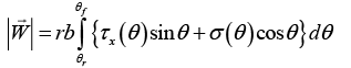
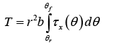
In conventional studies of surface locomotion of planetary rovers the interaction of wheels moving forward on terrain is based in semi-empirical laws, in which the more representative or dominant physics of the phenomenon are incorporated. This empirical approach is known as the approach of terramechanics [14] and validated experimentally in a controlled platform with measurements of the wheel-axis forces. To parametrize the motion of rovers in loose terrains. Figure 6. displays the general model of a wheel on deformable soil, along the forces, stresses and moments the terramechanics method allows to monitor. For simplicity, the wheel is assumed to be rigid. Along the contact path with the ground, the soil convey tangential and normal stresses (τ andσ , respectively) in order to balance the pressure transferred by the weight of the wheel during their displacement, as shown in Figure 6a. Given a constant forward velocity, by simple integration of τ (θ) and σ (θ) over the entire contact area, the normal and lateral forces represented in Figure 6b can be estimated [12,15,16]. The normal force that is balanced to the vertical load is given by the following:

Figure 6: Physical model of a wheel moving on deformable soil.
 (1)
(1)
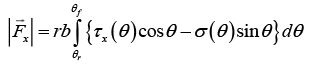
where r is the radius of the wheel, b is the width of the wheel, τx(θ) the tangential stress along the direction x in the contact pointθ , σ (θ) is the normal stress at θ , θr is the entry angle, and θf the final contact angle.
The expression for the drawbar pull or net tangential force Fx is given by [14]:
 (2)
(2)
In the other hand, the wheel’s driving torque can be estimated through:
 (3)
(3)
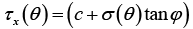
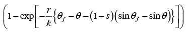
With knowledge of the normal and tangential stress distributions, together with the set of Eqs. (1)-(3), the forces and torques acting on the wheel can be completely resolved, leading to validate fundamental design concepts for rover locomotive systems. For the model of a wheel on a deformable soil the following formula has been established in the field of terramechanics for the tangential stress along the displacement axis of the center of mass of the wheel ("x"direction) [15,16]:
 (4)
(4)
c :Cohesion stress of the soil
φ : Internal friction angle of the soil
k : Share displacement under the wheel
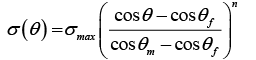
The determination of normal stress σ (θ) is relatively complicated, and several models have been proposed for better representation of the experimental data [12]. Assuming θm is the angle at which the maximum normal stress σmax(θ) is observed, the distribution profile for θm <θ <θf is as follows [17]:
 (5)
(5)
And it is symmetric for θr < θ < θm . In the analytical approach of terramechanics, an experimental validation of the aforementioned wheel-terrain interaction model is performed by means of a single wheel testbed. Experiments normally are carried out in a soil of known parameters with a lightweight rover wheel moving at a constant speed. The environment is controlled with an instrumented platform and advancing sensing devices are in charge of monitor the stress distributions τ and σ generated along the contact path angles θr and θf (presented by Eqs. (4)-(5)). The sensing devices and actuation mechanisms are presented in the following section.
Experimental validation
Sinkage is an important source of failure for most planetary rovers and strictly observed when soil layers collapse under a normal load. In a deformable terrain, rover wheels may suffer both severe slip and sinkage. In the worst case causing the rover to get stuck in the ground. In 2005, the rover Opportunity was stalled during its cruise through the Purgator Dune of Mars, requiring about 5 weeks to escape [18]. Apart from sinkage formation, wheels can slip in both longitudinal and lateral directions.
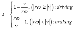
Let the slip ratio s be introduced as function of the ratio between the linear velocity v along an axis of the wheel to the circumferential velocity rω:
 (6)
(6)
with r the radius of the wheel. The slip ratio varies between -1 to 1, at the highest representing the wheels are rotating stalled with no forward motion. From the transverses of the Mars rovers, instances were observed while crossing highly deformable sulfate rich sands in which the wheel slip approached to 100% (s=1), occasioning technical problems and mobility difficulties [19,20]. For this reason, simulation of typical environments brings the need to include realistic conditions in typical single wheel platforms, in particular at situations when known standard terramechanics fail to predict mobility due to high slip conditions [21,22]. At TUBS’s Institute of Space Systems (IRAS) efforts are driven to build a locomotion testbed based on different concept designs, providing a solid basis for model improvement and correlations of planetary rover wheels. The testbed under concept phase and construction consists of a single, motor-driven wheel attached to a rigid vertical mount as shown in Figure 7. Two configurations are planned for 3D4 Space. In the first configuration (Figure 7a), experiments are carried at high slip ratios owing the wheel edge remains stationary and only a free vertical displacement is allowed. Further, a horizontal carriage controls the transversal motion of the platform, and different slip ratios can be adjusted through a screwdriven mechanism conferring a transversal, controlled accurate motion of the wheel, presented in Figure 7b. The testbed contains two motors and electronics with specifications provided in Table 2./p>
| Parameter | Value |
|---|---|
| Testbed dimensions(W × L × H) | 1395 mm × 1420 mm × 3120 mm |
| Soil | TUBS-M lunar regolith simulant |
| Sinkage measurement | Linear Encoder |
| Horizontal carriage | 90 W Maxon DC motor |
| Wheel motor | 200 W Maxon DC motor |
| Force measurements | 6-axis ATI F/T sensor |
| Torque measurements | Torque sensor Futek |
Table 2: Characteristics of the single wheel test-bed.

Figure 7: Single wheel testbed with adaptable configurations and instrumentation scheme.
The driving motor provides the wheel forward motion and it is embedded inside it. The horizontal carriage motor drives an screw driven actuator that imitates the influence of the vehicle body on the wheel in order to create different slip ratios. The wheel sinkage is represented as the depth that a rover sinks while driving through soil, and measured by a high-precision linear-potentiometer displacement sensor. The complete soil bin testbed includes lunar regolith simulant produced at the university (TUBS-M) and dimensions of 1.3 m width, 3.1 m length and 0.16 m width, conferring enough space for experiments to avoid boundary effects. The mechanical frame and the rail under construction is instrumented with a displacement sensor, six-axis force-torque (F/T) sensor, driving torque sensor and optical encoders. The F/T sensor incorporated in the wheel mount can measure vertical load and traction generated by the wheel, while the driving torque sensor measures the total torque applied to the wheel. The forward motion is limited up to 1m assuming light-weight rover wheels of typical diameters of 20 cm to 30 cm [23].
In-wheel sensing devices
Mobility is defined as the aptitude of a rover to perform displacements across an unprepared terrain [24]. This capability will depend on their carrying capacity to respond to hazardous situations imposed by the relief without compromising their overall stability. Experimental validation of the in-wheel characteristics in controlled single-wheel testbeds allows a reliable way to supply operational experiences for core planning of the activities of the rover. Owing the appropriate sensing devices are mounted at the exterior of the wheel to monitor the resulting forces and torques, the actual contact model can be validated. However, experience in the verification of the classical interaction model [25] have meet up instrumentation problems at the time to accurately determine the wheel sinkage, wheel contact angle or pressure distributions. The team of Nagatani et al. [26] suggested that devices embedded in the target wheel are required to measure some of these parameters or phenomena, without using external devices embedded in the environment. The team of Shirai proposed an in-wheel sensing system to complete that task [27]. Iagnemma et al. [28] proposed a correlation between the motor torque and wheel sinkage that can be studied through cameras and some information from the soil. Therefore, the mobility determination leaves room for improvement in the instrumentation and handling of experimental data.
In this work, we present the different preliminary concept models for in-wheel sensing devices permitting the automatic acquisition of the stresses at the contact point with the granular material. According the type of wheel, lug distribution and intersection, the apparatus can be advantageous to be incorporated in one or another case, providing in practice the best deal of available data. As the initial aim is to employ the methods validated in real environments, initial concepts for in-wheel sensors are roughly based on [27] and [29], and introduced in Figure 8. Because typical design of planetary rovers encounters wheels with plane surfaces and wheels with grousers, designs in Figure 8a show the concept of plane wheel with single-zone force sensor resistors along light sensor modules installed in the radial path.

Figure 8: In-wheel sensing devices for accurate measurements of the stress distributions and resistive forces.
The combined use of force and light detectors along a contact path within ~100° of radial area are used to determine the wheel contact angles while measuring the pressure distributions in real time. According the maximum weight of the vertical platform, the load range of the sensor has been chosen, corresponding to 20 N within a single-zone area of 5.1 mm diameter according the manufacturer [30]. Further, the KY-018 photoresistor module has been selected to measure the light intensity along the contact area. The digital output of the light sensor is binarized according the presence or absence of contact area with the ground, in a way the entry angles are measured with a resolution up to 4 (the angular distance between continuous sensors).
When the grouser is mounted on the surface of the wheels, the sinkage can be predicted via knowledge of the soil resistive force Fg . The sensor components are depicted in their original configuration presented in Figure 8b. [29]. The grouser is connected to the elastic part that lies inside the wheel, and strain gages are mounted into this surface. Via the rotational movement of the grouser, a resulting strain is generated into the elastic band, and sensed by the strain gage. The contacting angle of the grouser against the loose soil is determined from this value. Even the grouser mechanism is allowed to rotate along an axis, this movement is short and thus the proposed wheel has the same performance as a rigid wheel [29].
With the combined vertical platform weight, the equipment presented here are solutions well suited for determining the mobility of any type of rover wheel and that can be applied to any type of soil in our testing environment.
Conclusion
Deployment of an analogue mission demonstration for additive manufacturing of lunar regolith seems feasible within few years of aggressive development. In TUBS, basic research is performed across different disciplines and technology readiness levels (TRLs). In particular, new lunar soil simulants are under production and characterization to target potential applications of in-resource utilization (ISRU) in open extreme environments. Laboratory-based studies show the fidelity of the initial simulant production to match the basic physical properties of the mare and highland regions of the Moon. The present team has identified that at the current state of the art, several applications of ISRU with high impact on mission operations of future space missions still in speculative phase. Therefore, the 3D4 Space consortium promotes rapid progressing on new processing technologies of lunar regolith proved with molten optical transparent glass objects. A printing head of TUBS simulant is in current development and technology maturation (TRL-2 and TLR-3). The enabling robotic systems indispensable for in-situ operations of the manufacturing hardware has been preliminary sized yielding valuable information to reduce the mission risk, especially, in terms of mobility and locomotion capability to planning and drive a printing arm. The active research initiated in mobility of rovers focusses on developing more robust techniques to resolve and predict the intricate rover response in the field where substantial mechanical stability is desired, and an experimental platform to validate the basic contact models between planetary wheels and lunar simulant are in current development.
References
- Taylor LA, Carrier WD, Taylor GJ. The geotechnical properties of the lunar regolith: from equator to the poles. Abstract of Lunar regolith simulant materials workshop, Marshall Space Flight Center, Alabama, USA; 2005.
- Heiken G, Vaniman D, French BM. Lunar sourcebook: A user's guide to the moon, Cambridge, England: Cambrige University Press,UK;1991.
- Taylor LA, Pieters CM, Britt D. Evaluations of lunar regolith simulants. Planet Space Sci. 2016;126:1-7.
- 3D printing in space. The National Academies Press. Washington DC, USA; 2014.
- Colwell JE, Batiste S, Horányi M, et al. Lunar surface: dust dynamics and regolith mechanics. Rev Geophys. 2007;45.
- Gebhardt A. Generative Fertigungsverfahren. Munich: Carl Hanser Verlag; 2013.
- Luo J, Gilbert LJ, Qu C, et al. Additive manufacturing of transparent soda-lime glass using a filament-fed process. J Manuf Sci E. 2017;139.
- Klein J, Stern M, Franchin G, et al. Additive manufacturing of optically transparent glass. 3D Printing and Additive Manufacturing. 2015;2:3.
- Lennox J. Vision for space: The winding journey through life and the space program as seen by an ordinary joe. Lincoln. Nebraska: Universe, Inc; 2004.
- Cooper KG, Griffin MR. Microgravity manufacturing via fused deposition. NASA; 2003.
- https://www.nasa.gov/content/open-for-business-3-d-printer-creates-first-object-in-space-on-international-space-station
- Yoshida K, Mizuno N, Ishigami G, et al. Terramechanics-based analysis for slope climbing capability of a lunar/planetary rover. Proceedings of the 24th International Symposium on Space Technology and Science. Japan; 2004.
- Colwell JE, Batiste S, Horanyi M, et al. Lunar surface: Dust dynamics and regolith mechanics. Rev Geophys. 2007; 45(2).
- Siliciano B, Oussama K. Springer Handbook of Robotics. New Jersey, USA: Springer-Verlag New York Inc, USA; 2007:1271-2.
- Wong JY. Chapter 2. In: Theory of ground vehicles. John Wiley & Sons, NY, USA; 1978.
- Bekker G. Introduction to Terrain-Vehicle Systems. University of Michigan Press, USA; 1969.
- Yoshida K, Ishigami Y. Steering characteristics of a rigid wheel for exploration on loose soil. IEEE/RSJ International Conference on Intelligent Robots and Systems (IROS). 2004;4:3995-4000.
- Ding L, Gao H, Deng Z, et al. Experimental study and analysis on driving wheel´s performance for planetary exploraion rovers moving in deformable soil. J Terramechanics. 2011;48:27-45.
- Arvidson RE, Bell JF, Bellutta P, et al. Spirit Mars Rover Mission: Overview and selected results from the northern Home Plate Winter Heaven to the side Scamander crater. J Geophys Res. 2010;115.
- Sullivan RJ, Anderson R, Biesiadecki J, et al. Cohesions, friction angles, and other physical properties of Martian regolith from Mars Exploration Rover wheel trenches and wheel scuffs. J Geophys Res. 2011;116.
- Johnson JB, Kulchitsky AV, Duvoy P, et al. Discrete element method simulations of Mars Exploration Rover wheel performance. J Terramechanics. 2015;62:31-40.
- Johnson JB, Duvoy PX, Kulchitsky AV, et al. Analysis of Mars exploration rover wheel mobility processes and the limitations of classical terramechanics models using discrete element method simulations. J Terramechanics. 2017;73:61-71.
- Britton N, Walter J,Kazuya Y, et al. Four wheel rover performance analysis at lunar analog test. In: Result of the 10th International conference on Field and service robotics. Springer; 2006:361-71.
- Malenkov MI, Volov VA, Guseva NK, et al. Increasing the mobility of Mars rovers by improving the locomotion systems and their control algorithms. Russ Eng Res. 2015;35:824-31.
- Senatore C, Stein N, Zhou F, et al. Modeling and validation of mobility characteristics of the Mars Science Laboratory Curiosity Rover. In: The International Symposium on Artificial Intelligence, Robotics and Automation in Space; 2014.
- Nagatani K, Ikeda A, Sato K, et al. Accurate estimation of drawbar pull of wheeled mobile robots traversing sandy terrain using built-in force sensor array wheel. In: IEEE/RSJ International Conference on Intelligent Robots and Systems; 2009.
- Shirai T,Ishigami G. Development of in-wheel sensor system for accurate measurement of wheel terrain interaction characteristics. J Terramechanics. 2015;62:51-61.
- Iagnemma K, Kang S, Brooks C, et al. Multi-sensor terrain estimation for planetary rovers. In: Proceedings of the 8th international symposium on artificial intelligence, robotics, and automation in space. New York; 2003.
- Iizuka K, Tatsuya S, Satoshi S, et al. Study on grouser mechanism to directly detect sinkage of wheel during traversing loose soil for lunar exploration rovers. ROBOMECH J. 2014;1(1):15.
- http://www.interlinkelectronics.com/FSR400.php