Original Article
, Volume: 13( 1)Holdups in a Three-Phase Fluidized Bed with Angled Disc Promoter
- *Correspondence:
- Ramesh KV Department of Chemical Engineering, Andhra University, Vizianagaram, Andhra Pradesh, India
Tel: +91-9490109683; E-mail: kvramesh69@yahoo.com
Received Date: January 12, 2018 Accepted Date: February 9, 2018 Published Date: March 15, 2018
Citation:Reddy GVSK, Ravindra Kumar K, Ramesh KV. Holdups in a Three-Phase Fluidized Bed with Angled Disc Promoter. Chem Technol Ind J. 2018;13(1):120.
Abstract
Experiments were conducted to investigate the effect of pertinent dynamic and geometric variables on gas and liquid holdups in a three-phase fluidized bed in the presence of an angled disc promoter. The gas holdup was found to be increasing with pitch, disc diameter and disc angle. The gas holdup decreased with variation in particle diameter. The liquid holdup was found to be decreasing with an increase in pitch, particle diameter and disc angle. The liquid holdup increased with increasing disc diameter. The data on gas and liquid holdups were correlated using least squares regression analysis to obtain useful correlations
Keywords
Holdup; Angled disc promoter; Three phase fluidized bed
Introduction
Three-phase fluidized beds offer the advantages of high macromixing, high reactant conversions, uniform temperature and so on [1]. Hence, effective contact between the phases can be best achieved in a three-phase fluidized bed and it could be the best option that suits to the needed requirements. It has been found that disc promoter offers the advantage of yielding high heat and mass transfer rates in homogeneous flow [2], liquid fluidized beds [3], gas-liquid up flow bubble columns [4] and three phase fluidized beds [5]. But the disc promoter has the disadvantage of yielding fluctuating values of mass transfer coefficients in axial direction. This can be overcome by employing angled disc promoter [6-9]. Although three phase fluidized beds often yield highest values of heat and mass transfer coefficient values, it is also important to know the behaviour of phase holdups because of their prominence in design calculations [10-13]. In view of this, investigations have been carried out by the authors to study the effect of pertinent dynamic and geometric variables on individual phase holdups in a three-phase fluidized bed in the presence of angled disc promoter elements. Also, an attempt is made to develop generalized correlations for gas and liquid holdups through empirical modelling using appropriate dimensional groups involving flow variables and geometrical parameters. The range of variables covered in the present study are given in Table 1.
| S. No. | Parameters studied | Minimum | Maximum | Max/min |
|---|---|---|---|---|
| 1 | Velocity of gas, Ug [m/s] | 0.014 | 0.070 | 5 |
| 2 | Velocity of liquid, UL [m/s] | 0.0468 | 0.234 | 5 |
| 3 | Promoter rod diameter (dr × 102), m | 0.6 | 1.3 | 2.16 |
| 4 | Pitch between the discs (p × 102), m | 3.0 | 10.0 | 3.33 |
| 5 | Diameter of the disc (dK × 102), m | 3.0 | 6.0 | 2.0 |
| 6 | Diameter of the particle (dp × 103), m | 2.931 | 5.623 | 1.79 |
| 7 | Disc angle (θ), degrees | 0 | 67.5 | - |
| 8 | Reynolds Number, Re | 3598 | 22235 | 6.17 |
| 9 | Particle Reynolds Number, Rep | 266 | 1852 | 6.96 |
Table 1. Range of variables covered in the present study.
Nomenclature
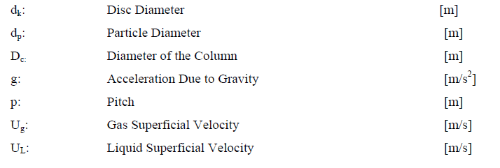
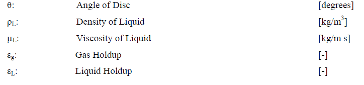
Greek Symbols
Dimensionless Groups
Frg=Froude number based on gas velocity 
Re=Reynolds number 
Rep=Reynolds number based on particle diameter 
Experimental
The schematic of the experimental setup used in the present investigation was shown in Figure 1. The equipment and apparatus consisted of a storage tank (S), centrifugal pump (P), two rotameters (R1 and R2) and a nitrogen cylinder (N) along with regulator (R). A U-tube manometer (U) was provided to measure the pressure difference across the test section (B). Valves V1 to V8 were employed to regulate the flow rates of fluid. The diameters of the glass balls were 2.93, 4.24 and 5.62 mm. These balls were used as bed med material. An electrolyte belonging to ferry-ferry redox system has been used as liquid phase. This electrolyte has been chosen as liquid phase in the present study because it is widely used in electrochemical studies and its physical properties are near to water properties. Nitrogen was employed as gaseous phase. The storage tank was of 100 litres capacity. To measure the liquid and gas flow rates, the rotameters R1 and R2 were used respectively. The experimental column shown in Figure 1 mainly consisted of three sections: an entrance calming section (A), a test section (B) and an exit section (C). The entrance calming section (A) was made of a copper tube of 6.73 cm inner diameter, outer diameter of 7.62 cm and 1.07 m long. The test section (B), which was the electrochemical cell, 0.6 m height. In the U-tube manometer, two pressure taps, (T1) and (T2) were used to measure the manometer difference in the test section of the column. The promoter elements of different geometric characteristics (viz., diameter of copper rod dr, pitch p, diameter of the angled disc dK and angle of disc θ) were fabricated and used in the present studies.

Figure 1: Schematic diagram of the experimental unit.
Measurement of bed height facilitates the computation of solids holdup.
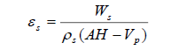 ... (1)
Holdup is obtained from pressure drop as
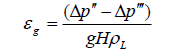 ... (2)
Liquid holdup is then calculated as 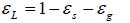 ... (3)
Results and Discussion
In the present investigation, the influence of the geometrical parameters of the angled disc promoter on gas and liquid holdups in a three-phase fluidized bed is examined and the corresponding graphical analysis is reported here under for the cases of varied pitch, disc diameter, disc angle and particle diameter.
Gas holdup
The data on gas holdup were plotted against superficial liquid velocity for three different disc diameters viz. 3.0, 4.5 and 6.0 cm for the promoter at a constant superficial gas velocity Ug=0.0327 m/s, and the resulting graph is shown in Figure 2. From an observation of the plots of this figure it can be found that the gas holdup increased with increasing disc diameter. As the disc diameter increases, the size of the wage increases, and the wake retains more gas. Thus, an increase in gas holdup is seen with increase in disc diameter. Same trends are also evident from the inset figure Figure 2. From an inspection of the plots it can be found that the gas holdup increased with increasing disc angle from 0 to 67.5 degrees as shown in Figure 2. and its inset Figure 2. The reason for this trend is as follows: as the disc angle is increased, the obstruction area, which is the projected area normal to the flow direction decreases. Therefore, the size of the wakes gets reduced. This leads to decreased intensity in the churning action generated by the wakes. Thus, more gas is retained in the bed yielding more gas holdup at higher inclination. Figure 2 shows the gas holdup data plotted against superficial liquid velocity for three particle sizes viz, 2.93, 4.24 and 5.62 mm in the case of angled disc promoter at a constant superficial gas velocity Ug=0.0234 m/s. The plots reveal that the gas holdup decreased with the diameter of particles. This trend is also evident from its inset Figure 2. An increase in liquid velocity causes the fluidized bed to expand. As the particle diameter is increased, at a given liquid velocity more number of solid particles present in the given volume of the bed. This causes a reduction in the gas holdup. This mechanism is in accordance with the trends observed in this graph. In case of increasing gas velocity at a fixed liquid velocity, the variation in bed expansion would be insignificant. Because, the suspension of particles in the bed is mainly due to liquid momentum and the gas momentum hardly adds to it. Hence, the effect of particle diameter in this case can be expected to be small.

Figure 2: Variation of gas holdup with pitch, disc diameter, disc angle and particle diameters.
Liquid holdup
Figure 3a shows the liquid holdup data plotted against superficial liquid velocity at a constant superficial gas velocity Ug=0.0327 m/s. A close examination of the plots of the figure reveals that the liquid holdup decreased with increasing pitch and this trend is also conspicuous from the inset Figure 3. And Figure 3 shows the liquid holdup data plotted against superficial liquid velocity for three different disc diameter values viz., 3.0, 4.5 and 6.0 cm in the case of angled disc promoter at a constant superficial gas velocity Ug=0.0327 m/s. It can be observed from the plots of this figure that the liquid holdup increased with increase in disc diameter as is evident from the inset Figure 3. A close inspection for liquid holdup against gas velocity for the same promoter geometry reveals no significant effect of disc diameter on liquid holdup when the gas velocity is varied. Figure 3. shows the liquid holdup data plotted against superficial liquid velocity for three different disc angles viz, 0, 22.5 and 67.5 degrees in the case of disc promoter at a constant gas velocity Ug=0.0327 m/s. A close examination of the plots of the figure reveals that the liquid holdup decreased with increasing disc angle and this observation is also conspicuous from inset Figure 3. Figure 3. shows the liquid holdup data plotted against superficial liquid velocity for three different particle sizes viz., 2.93, 4.24 and 5.62 mm in the presence of angled disc promoter at constant superficial gas velocity Ug=0.023 m/s. Inspection of these plots reveals that the liquid holdup decreased with particle diameter is conspicuous from inset Figure 3.

Figure 3: Variation of liquid holdup with pitch, disc diameter, disc angle and particle diameters.
Correlation
The data obtained on gas and liquid holdups were correlated using least squares regression analysis and the following correlations were proposed (Table 2).
| S. No. | Correlations proposed | Equation no. |
|---|---|---|
| 1. | 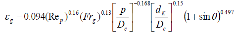 Average deviation=10.79%; Standard deviation=12.68% |
(4) |
| 2. | 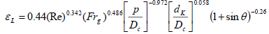 Average deviation=10.37%; Standard deviation=14.15% |
(5) |
Table 2. Correlation obtained.
Conclusion
Measurement of bed height and pressure drop facilitated the computation of individual phase holdups in a three-phase fluidized bed in the presence of coaxially placed angled disc on a rod. The gas holdup increased with pitch, disc diameter, disc angle and decreased with particle diameter. The liquid holdup decreased with pitch, disc angle and particle diameter and increased with disc diameter. Useful correlations were obtained for gas and liquid holdups in terms of dimensionless groups and geometrical parameters of the promoter element.
Acknowledgements
The authors express they’re thanks to Late Mr. B. Niranjana Rao, Assistant Professor, Department of Chemical Engineering, GMR Institute of Technology, Rajam-532127, India, for his continuous help during experimentation.
References
- Fan LS. Gas liquid solid fluidization engineering. Butterworths-Heinman. 1989.
- Venkateswarlu P, Gopichand T, Jaganadha Raju GJV. Increased mass transfer in a circular column in the presence of disc promoter. J Energy Heat and Mass Transfer. 2000;22:195-203.
- Ravi T, Srinivasa Rao B, Gopala Krishnna P, et al. Ionic mass transfer studies in fluidized beds with coaxially placed discs on a rod as internal. Chem Eng Processing. 1996;35:187-93.
- Sarma GVS, Murty MSN, Ramesh KV, et al. Wall to bulk mass transfer in gas liquid up flow bubble column with disc promoter. J Energy Heat and Mass Transfer. 2011;33:233-49.
- Murty MSN, Ramesh KV, Venkateswarlu P, et al. Ionic mass transfer in three-phase fluidized beds in the presence of disc promoters. Chemical Engineering Communications. 2011;198:1018-32.
- Niranjana Rao B, Rama Prasad BSG, Murty MSN, et al. Mass transfer at the confining wall of an electrochemical cell in the presence of angled disc promoter. American J Heat and Mass Transf. 2014;1:113-29.
- Niranjana Rao B, Rama Prasad BSG, Murty MSN, et al. Wall-to-bed mass transfer in a fluidized bed electrochemical reactor in the presence of angled disc promoter. AIChE Spring Meeting. 2015;26-30.
- Rama Prasad BSG, Niranjana Rao B, Ashok Kumar K, et al. Mass transfer in a gas-liquid up flow bubble column in the presence of angled disc promoter. Chem Technol: An Indian Journal. 2016;11(5):1-9.
- Rohini Kumar P, Ashok Kumar K, Murty MSN, et al. Wall-to-bed mass transfer in three-phase fluidized bed in the presence of an angled disc promoter. J Heat and Mass Transfer. 2017;53(10):3129-40.
- Ramesh KV, Raju GMJ, Sarma GVS, et al. Effect of internal on phase holdups of a three-phase fluidized bed. Chem Engg J.2009;145:393-8.
- Murty MSN, Ramesh KV, Prabhakar G, et al. Phase holdups in three-phase ?uidized beds in the presence of disc promoter. Experimental Thermal and Fluid Science. 2011;35:338-46.
- Subramanyam BS, Murty MSN, Surendra Babu B, et al. Phase holdups in three-phase fluidized beds with twisted tape internal. Multiphase Science and Technology. 2016;28(1):53-70.
- Rohini Kumar P, Ramesh KV, Venkateswarlu P. Phase holdups in a three-phase fluidized bed in the presence of coaxially placed string of spheres internal. IOP Conference Series: Materials Science and Engineering. 2017;225:012210.