Short communication
, Volume: 19( 1)Design and Modeling of Cyclotron Proton Circuit with Helium Source
Erfan Ghapanvari*, Marzieye Nadi, Fateme Zaheri
Department of Physics, Malayer University of Iran, Iran
- *Correspondence:
- Erfan Ghapanvari
Department of Physics, Malayer University of Iran, Iran
E-mail:E-mail:ghapanvarierfan@gmail.com
Received: August 09, 2023, Manuscript No. TSNSNT-23-109930; Editor assigned: August 14, 2023, PreQC No. TSNSNT-23-109930(PQ); Reviewed: August 29, 2023, QC No. TSNSNT-23-109930; Revised: January 18, 2025, Manuscript No. TSNSNT-23-109930(R); Published: January 25, 2025, DOI:10.37532/0974-7516.2025.19(1).001
Citation: Ghapanvari E, Nadi M, Zaheri F. Design and Modeling of Cyclotron Proton Circuit with Helium Source. Nano Tech Nano Sci Ind J. 2025;19(1):001.
Abstract
Today, the need to build high high-energy and efficient accelerators for laboratory and industrial work is more than ever. In this article, we investigate and model the behavior of protons inside a cyclotron with a helium source, which releases protons through the ionization process of electric discharge. helium source as a new source for cyclotron increases productivity. we will examine all method s and positions, as well as kinetic energy and phase change. the amount of electric and magnetic field considered in this accelerator is experimental and operational.
Keywords
Modeling cyclotron cyclotron; Proton ci rcuit; Helium source source; Protons bunch
Description
The proton cyclotron circuit is an essential component of a cyclotron, responsible for the acceleration of protons. The circuit consists of a series of magnetic fields and electric potentials that guide and accelerate the protons. In this design, a helium source is used to provide the necessary ion source for the cyclotron. The helium source is chosen due to its high ionization potential, which allows for the generation of a high-energy beam of protons [1].
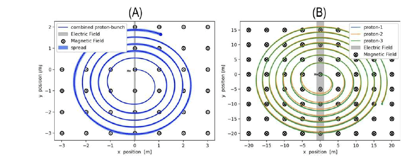
Designing a cyclotron proton circuit with a helium source requires accurate simulation and modeling. This is done using computer simulations, which allow for the optimization of the various components of the circuit. The simulation and modeling process includes the optimization of the magnetic field strength, the RF cavity frequency, and the electric potentials (Figure 1).
FIG 1: (A) It shows the spread of protons in different cyclotron orbits. (B) The movement path of three hypothetical protons is determined based on their position in the x, y diagrams, as well as the effect of electric and magnetic fields on the behavior of protons.
Modeling the helium source
To ensure the optimal performance of the helium source, accurate modeling is essential. Through computational simulations and modeling techniques, the behavior of the helium source can be analyzed under various operating conditions. These models take into account factors such as gas flow, plasma characteristics, and magnetic fields to accurately predict the helium source's performance.
The modeling process involves solving complex equations and simulating the ionization and extraction processes within the source. By iteratively refining the model parameters, researchers can optimize the helium source design and improve the overall efficiency of the cyclotron system.
The basics of helium ionization
Helium, with its complete shell of electrons, does not readily accept additional electrons or form covalent compounds. Its first ionization energy, the energy required to remove an electron, is the highest among all elements. Additionally, helium's electron affinity, the energy change when an electron is added, is close to zero. These factors contribute to helium's unreactive nature [2].
However, at extremely low temperatures, weak van der Waals forces can overcome repulsive forces between helium and other atoms, leading to the formation of van der Waals molecules. Moreover, under high pressures, helium can form crystalline compounds with certain elements such as sodium, suggesting that suitable pressures for solid combinations of helium might exist within planets.
Proton acceleration
Once the helium ions are generated, they are accelerated using a series of electric potentials and magnetic fields. The first stage of acceleration is the Radiofrequency (RF) cavity, which provides the initial acceleration of the ions. The RF cavity consists of a series of metal plates that produce an alternating electric field, which accelerates the ions [3].
After the RF cavity, the ions enter the cyclotron magnet, where they are accelerated further. The cyclotron magnet consists of a series of alternating magnetic fields, which guide the ions in a circular path. As the ions travel through the magnetic field, they are accelerated by the changing electric potential.
Helium recovery
After the protons have been accelerated, the helium ions need to be recovered. This is done using a helium recovery system, which captures the helium ions and recycles them back into the ionization chamber. The helium recovery system is designed to minimize any potential loss of helium, ensuring that the system remains efficient and cost- effective [4].
Beam transport and delivery
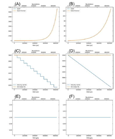
Once the protons have been accelerated, they need to be transported to the target. This is done using a series of electromagnets, which guide the beam to the target. The beam transport system must be carefully designed to ensure that the beam remains focused and does not scatter, which could lead to a loss of beam intensity (Figure 2).
FIG 2: (A) Fractional kinetic euler with fractional kinetic cromer compares according to time. (B) Fractional momentum euler with fractional momentum cromer compares according to time. (C) Fractional kinetic verlet with fractional kinetic r compares according to time. (D) Fractional momentum verlet with fractional momentum rk4 Compares according to time. (E) Euler cromer kinetic has drawn according to time. (F) Euler cromer momentum has drawn according to time.
Analyse period
In this section, we test the simulated time course of a proton in a cyclotron against it.
Expected time period provided by:
T=2πm/qB
The table below contains about 97 rounds Then the average of the time period and its error (a standard deviation) and the value are written below the table The time period predicted by the above equation. Finally, it gives us the ratio of two time periods Simulated time period divided by theoretical period (Table 1).
| Revolution | ... | Position(x) | (y) | (z) | |
|---|---|---|---|---|---|
| 0 | 0 | ... | 0 | 0 | 0 |
| 1 | 1 | ... | 0.025002006202 | 0.704039079 | 0 |
| 2 | 2 | ... | 0.045744619 | 1.2272292619 | 0 |
| 3 | 3 | ... | 0.033180411 | 1.65209242 | 0 |
| 4 | 4 | ... | 0.0602316047 | 2.02053990 | 0 |
| . | . | . | . | . | . |
| . | . | . | . | . | . |
| 93 | 93 | ... | 0.00130603427 | 4.43978781 | 0 |
| 94 | 94 | ... | 0.0357271359 | 4.49769385 | 0 |
| 95 | 95 | ... | 0.01472997294 | 4.540285423 | 0 |
| 96 | 96 | ... | 0.0469467733 | 4.55386371 | 0 |
| 97 | 97 | ... | 0.050283357 | 4.5493875 | 0 |
Time period from simulation: 0.0042 ± 0.0007 sec
Time period from theory: 0.0041 sec
Raito of simulated time period to theoretical: 1.0233
Analyse phase
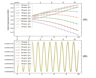
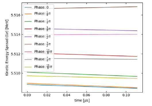
In this part, we analyze several different electric field phase changes in a cyclotron, then draw it The expansion of the y position of a proton bunch as well as the expansion of the kinetic energy of the bunch versus time. Contains the position and kinetic energy expansion for a proton cluster that contains 100 protons in about 10 rounds (Figure 3).
FIG 3:(A) It shows the release of kinetic energy for different phases with the time it takes. (B)It shows the time series for changing different phases.
Analyse cyclo phase
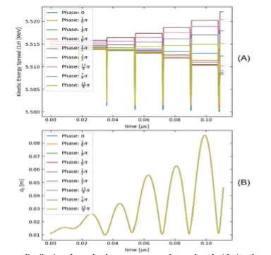
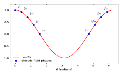
This analysis analyzes several different electric field phase changes in a cyclotron. then it will the expansion of the y position of a proton bundle as well as the expansion of the kinetic energy of the bundle vs time. It then fits a linear curve to the energy spread to plot changes in the spreads versus time can be visualized more easily. containing the position and distributed kinetic energy for a cluster containing protons100 protons in about 10 rounds (Figure 4-6).
FIG 6: The cosine axis is drawn for the theta angle from 0.2 to 1000 for the electric field of different phases.
Analyse time step
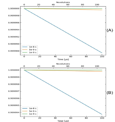
In this part, we analyze how the time step affects the accuracy of the simulation. It will register a cyclotron The simulation is performed using the Velocity Verlet method using three different time steps. Then he draws the fraction Kinetic energy and momentum versus time for each time step (Figure 7).
FIG 7: (A) fractional momenta in terms of time for three time steps 1e-8 s, 5e-9 s, 1e-9 Simulates. (B) fractional energies in terms of time for three time steps 1e-8 s, 5e-9 s, 1e-9 s Simulates.
Plot positions
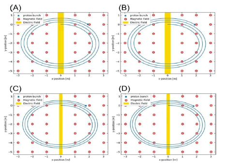
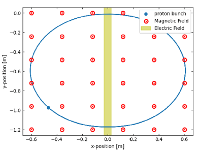
In this part of the simulation, we draw the path of the proton bundle in a cyclotron and show the electric current [5]. The field and direction of the magnetic field are defined in the input data files (Figure 8).
FIG 8: (A) It shows Euler's method for simulating the position of each proton in the cyclotron in the presence of magnetic and electric fields. (B) It shows the Euler-Cromer method for simulating the position of each proton in the cyclotron in the presence of magnetic and electric fields. (C) This method shows the Verlet velocity to simulate the position of each proton in the cyclotron in the presence of magnetic and electric fields. (D) It shows the fourth-order Rang-Kutta method for simulating the position of each proton in the cyclotron in the presence of magnetic and electric fields.
Kinetic energy
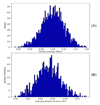
Kinetic energy and average kinetic energy shows in Figure 9. The simulation shows the position of a proton in a cyclotron in the presence of magnetic and electric fields shows in Figure 10.
FIG 9: (A) It shows the relationship between the number of protons and the kinetic energy in a cyclotron, as it is known that the kinetic energy is different for a certain number of protons. (B) It shows the relationship between the number of particles and the average kinetic energy in a cyclotron, as it is clear in the figure, the average kinetic energy is different for a certain number of particles.
FIG 10: The simulation shows the position of a proton in a cyclotron in the presence of magnetic and electric fields.
Conclusion
As a result, the design and modeling of the proton cyclotron circuit with helium source is a complex process that requires a detailed investigation of various factors such as phase change methods and time analysis as well as the position of protons. Helium source ionization, proton acceleration, helium recovery, and optimization of various components are all critical aspects of the design. With careful simulation and modeling, an efficient and effective proton cyclotron circuit with a helium source can be created, providing a high-energy beam of protons for various applications.
Declaration of Competing Interest
The authors declare that they have no known competing financial interests or personal relationships that could have appeared to influence the work reported in this paper.
References
- Batchelor R, Aves R, Skyrme THR. Helium?3 Filled Proportional Counter for Neutron Spectroscopy. Rev Sci Instrum.1995;26 (11):1037-1047.
- Carter JJ. Analysis of a direct energy conversion system using medium energy helium ions (Doctoral dissertation, Texas A&M University). 2006.
- Lawrence EO, Livingston MS. The production of high speed light ions without the use of high voltages. Phys Rev. 1932;40(1):19.
[Crossref]
- Lou W, Mayes C, Cai Y, White G. Simulating two dimensional coherent synchrotron radiation in python. In Proc. 12th Int. Particle Accelerator Conf.(IPAC’21) 1921:3177-3180.
[Crossref]
- Petrov YV, Vyvenko OF. Secondary electron generation in the helium ion microscope: basics and imaging. Helium Ion Micros. 2016:119-146.
