Mini Review
, Volume: 12( 1) DOI: DOI. 10.37532/2320ââ¬â6756.2023.12(1).253Potential route for the construction of a super massive space habitat
- *Correspondence:
- Mark Waterman Editorial office , Journal of Space Exploration, United Kingdom E-mail: mark@watermandesign.co.uk
Received date: 17-January-2023, Manuscript No. tsse-23-87205; Editor assigned: 19-January-2023, PreQC No. tsse-23-87205 (PQ); Reviewed: 23-January-2023, QC No. tsse-23-87205 (Q); Revised: 26-January-2023, Manuscript No. tsse-23-87205 (R); Published: 28January-2023, DOI. 10.37532/2320–6756.2023.12(1).253
Citation: Waterman M. Potential Route for the Construction of a Super Massive Space Habitat, J Space Explor.2023; 12(1).253.
Abstract
In considering practical routes to achieving the objective of producing a supper massive space habitat there appears to be three main challenges: power, raw materials and manufacturing method and associated facilities. Whilst these factors are interconnected and possible solutions to the first two are discussed the main purpose of this document is to propose a method of manufacturing that is thought to be the simplest possible and provides multiple associated benefits such as increased speed and reduced cost and risk.
Keywords
Space habitat; Catalytic fission; Dirac chord; Magnetic charge; Magnetic dipole; Magnetic monopole annihilation
Introduction
When considering the construction of huge space habitats there are many reasons why simplicity is a major advantage. The proposed method is thought to be the simplest possible way of constructing a large orbital ring structure. There are virtually no facilities required and minimum assembly operations [1] (FIG. 1).

Figure 1: Artists impression of giant space habitat.
The habitat is manufactured in one piece, using an additive manufacturing process that utilises the advantages of zero gravity and vacuum (zero friction) [2]. A print head floats in position next to a thin, narrow, Seed Ring and deposits material onto the ring as it rotates (FIG. 2).

Figure 2: Additive manufacturing process involving deposition of material onto rotating seed ring.
The print head moves sideways a small amount on each revolution and then inwards slightly towards the ring centre when that layer has been printed. An enclosed torus structure can then be constructed that is much bigger than the Seed Ring it started from. Services (gas, liquid, power) can all be incorporated into the design (FIG. 3) with different materials printed concurrently. With appropriate use of removable supports that can be reused for other purposes, internal compartments, bulkhead and doors can also be created ready for final finishing and assembly. There are no constraints to constructing in this manner to nearly the centre of the ring (the print head prevents full coverage) and for creating hollow spokes to connect to a central hub.

Figure 3: Example sectional view of space habitat showing how internal structures and other features can be incorporated into the design. Note the structure is oval rather than circular due to print overhang limitations – this will depend on the process used.
The initial orbital build phase involves the assembly of the Seed Ring upon which are mounted suitable thrusters to enable it to rotate about its central axis (FIG. 4). The Print head is manoeuvred into position and deposits material onto the inside surface of the ring which then grows and size from the outer edge inwards.

Figure 4: Progression of manufacture over time shown in stages.
The relationship between the required surface speed to induce gravitational levels of 0.5 g and 1g is shown in (FIG. 5). The implications are that unless printer speeds can be achieved that are hundreds of time greater than that used today for terrestrial printing today there will be no appreciable gravity induced during the construction phase.

Figure 5: Surface velocity (print head speed) required to achieve.
A spin off benefit of this approach is simplicity of design, there are considerably less components, tolerances and interfaces when compared to traditional orbital structures. Reducing complexity through fewer components reduces cost, risk and time (FIG. 6). It is easily possible to see how an enormous (multi-material) structure that would provide the backbone of environmental safety/ power/life support/hvac/services/gas storage/transportation and could be designed without a prohibitively large engineering team and using current design tools and methodologies (which will obviously continue to improve). There are significantly less interfaces to consider than if the construction was in separate sections. Large changes in design are possible after construction has commenced and final landscape design is only required half-way through the build.

Figure 6: Complexity of alternative approaches compared to cost, risk and time. The image on the right [2] credit: Deep Space Industries).
It is difficult to imagine the design and manufacturing control effort required if an enormous ring was constructed in space in sections and fitted together. The manufacturing infrastructure for this undertaking is equally mind blowing.
Print head
There are multiple terrestrial 3D printing processes which include Material Extrusion or Fused Deposition Modelling (FDM), Vat Polymerization (SLA DLP), Power Bed Fusions (SLS), Material Jetting (DOD), Binder Jetting, Power Bed Fusion (Direct Metal Laser Sintering (DMLS) and Selective Laser Melting (SLM) that use a laser beam to fuse metal powder layer by layer).
Three potentially viable processes are briefly considered, the injection nozzle does not have to be a single hole design shown. Multiple nozzles arranged in a line at increasing heights would potentially allow greater print depth.
A variant of the Fused Deposition Modelling process is based upon a filament that is a combination of thermoplastic material and metallic particles (FIG. 7). The filament is fed into a melt chamber and then directly through a nozzle on the ring. A laser is then used for localised sintering.

Figure 7: Fused deposition modelling process where a combination thin layer of is deposited in front of a laser than fuses it to the surface below. This process is not thought to be suitable for overhangs – e.g. the initial ring outer edge growth.
A variant of the Powder Fusion Sintering process uses metal power fed onto the surface of the ring directly in front of a laser capable of melting the powder and fuse it to the surface below (FIG. 8).

Figure 8: Powder Fusion process where a thin layer of is deposited in front of a laser than fuses it to the surface below. This process is not thought to be suitable for overhangs – e.g. the initial ring outer edge growth.
In order to generate the overhang required to grow the structure outwards from the seed ring it seems improbably that a powdered sintering process could be used as there will be nothing for the material to adhere to. The process could however be used inside of walls manufactured using one of the other processes and where the powder would be contained before fusion [3].
Another variant of the Fused Deposition Modelling process uses direct extrusion of the molten material from suitably insulated melt vessel. This process would likely require more energy than the laser bonding processes [4] (FIG. 9).

Figure 9: Direct extrusion process where molten material is forced through a Print Head nozzle onto.
As a minimum the Seed Ring needs to be just thick and wide enough to enable the print to start without any distortion and fitted with appropriate thrusters and directional control systems. Deposition of material will cause the ring to slow down so thrusters may be required to maintain rotation. This effect should reduce as the station gains angular momentum through increased mass. However, depending on the angle at which the material is deposited on the to the ring there could also be a force component in the direction of rotation which could potentially then power continued rotation.
To ensure the first layers adhere to the outer ring it would make sense to ensure the inner surface of the Seed Ring has appropriate keying features.
One further advantage of this method of manufacture is that the print head has virtually no acceleration as it is static for the majority of the print and only move very small amounts. This means that any print speed limitations that might have arisen from print head inertia such as with a Cartesian configuration are not relevant.
To test the basic print concept in a terrestrial environment a prototype FDM machine shown in FIG. 10 has been constructed. Although the design coding has yet to be completed several layers of material were able to be bonded to the inside surface during test runs.

Figure 10: Concept test prototype.
To test the basic logic in terms of power / materials / time etc. a simple model has been constructed and three versions of the ring considered, 100 m, 1 km and 10 km. There are no constraints in the model and it is possible to change some of the variables to create a ring in a ridiculously short period of time. In practice governing factors for larger rings are likely to be power availability, materials availability and flow rate limitation on the print head. There is also the not inconsequential challenge of ferrying very large quantities of people in sensible timescales.
Result
The first ring considered is 100 m in diameter, of a size thought potentially appropriate for support to activities outside of earth’s orbit within the solar system (FIG. 11).

Figure 11: Potential uses of multiple purpose facility including support to Mars or Lunar missions and support for commercial mining activities that may be required for super large habitat construction.
There are clearly benefits in having a facility that can used throughout the solar system and that can perform multiple roles. It is expected that the main structure would include bulkheads, floors, all services (power, gases, liquids) piping, gas and liquid storage and doors (prior to fitment of seals) [5].
Clearly with a print depth in mm it is not going to be possible to generate good mating surfaces and it is expected that appropriate filling and bonding techniques would be used where interfaces are required to connect to the internal facilities. All internal surfaces can be accurately scanned during manufacture to allow mating parts to be manufactured.
TABLE 1 shows three similar options with values in the unshaded cells. Calculated or referenced values are indicated in the shaded cells.
TABLE 1. Main dimension calculated for a ring of 100 m in diameter. Three versions have different external wall thicknesses from 20 mm– 100 mm
| Dimensions | Units | Option 1 | Option 2 | Option 3 | ISS | Notes |
|---|---|---|---|---|---|---|
| Outer Diameter [4] | m | 100 | 100 | 100 | 73 | Inside diameter of the Seed Ring. ISS dimension relates to maximum length |
| Section Outer Diameter | m | 10 | 10 | 10 | Outside diameter of the section - for the purposes of simplicity assumed to be circular | |
| Inner Diameter | m | 80 | 80 | 80 | ||
| Wall Thickness | m | 0.02 | 0.05 | 0.1 | ||
| Additional Print Area | % | 2 | 2 | 2 | For further inner floors / walls as a percentage of the central floor section area | |
| Internal Volume | m3 | 21842 | 21299 | 20406 | 932 | |
| Total Print Volume | m3 | 365 | 908 | 1801 | ||
| People on Board | 50 | 50 | 50 | 6 | ||
| Average volume per person | m3 | 437 | 426 | 408 | 155 | |
| Floor Space per person at 2.5 m ceiling | m2 | 175 | 170 | 163 | Approximate calculation does not consider curvature of structure |
A Ring of this size has 22 times the internal volume of ISS and with 50 people of board would offer 400 m3 of space per person compared to 155 in the ISS (both these numbers exclude space requirements for facilities, equipment etc. and should not be considered personal living space). Different wall thicknesses are considered ranging from 20 mm to 100 mm.
Print volume is calculated by subtracting the torus volume generated by the internal dimensions from that generated by the external dimensions and then adding additional volume for internal features and print supports, assumed as a percentage of the volume occupied by the central floor (a cylinder). Print volume is used to calculate mass and flow rates [6]. Total Sectional Area is calculated by adding the area of the section shown in blue in FIG. 12 to the floor area section and additional area for internal features and print supports. This is used later in to calculate print time.

Figure 12: Approximate calculations for total sectional area or swept area.
Ring material and associated mass and launch factors are shown in TABLE 2. Options 1 and 2 consider an Aluminium structure, Option 3 considers one made from High Density ABS (as a proxy for a plastic structure of material tbd).
TABLE 2. Materials selected and associated impact on total mass and shipping costs.
| Materials | Units | Option 1 | Option 2 | Option 3 | ISS | Notes |
|---|---|---|---|---|---|---|
| Main Structure Material | Aluminium | Aluminium | High Density ABS | |||
| Material Density | kg/m3 | 2705 | 2705 | 1100 | ||
| Wall Design Density | % | 0.5 | 0.5 | 0.5 | ||
| Total Mass | Tonnes | 494 | 1228 | 991 | 420 | |
| Raw Materials Production Rate | tonnes | 0.3 | 0.2 | 0.2 | ||
| /day | ||||||
| Falcon Heavy Lifts | 8 | 19 | 15 | 64 Ton lift capacity | ||
| Lifts frequency | days | 201 | 272.3 | 337.4 | ||
| Lift Cost | $bn | 1.2 | 2.9 | 2.3 | Assumed $150m per launch |
Materials production rate and lift frequency based upon the manufacturing characteristics is well within near term or current capabilities.
Average wall density impacts the mass calculations and launches but not the total print time as it is assumed that the swept area is the same as for a solid.
Print time is calculated by combining the geometric properties of the habitat, specifically the swept area with the size of the nozzle and the print speed as shown in FIG. 13.

Figure 13: Calculations of total time. Total Sectional Area= Swept Area.
TABLE 3 covers the manufacturing process with four key input variables print head speed, nozzle diameter and print depth used to determine the rotational speed of the ring during printing and the approximate print time.
TABLE 3. Calculation concerning the manufacturing process. Input variables are constant for each of the options.
| Manufacturing | Units | Option 1 | Option 2 | Option 3 | ISS | Notes |
|---|---|---|---|---|---|---|
| Print Speed | m/s | 0.5 | 0.5 | 0.5 | How fast the printer head moves relative to the surface being printed | |
| Nozzle Diameter | mm | 4 | 4 | 4 | Current home 3D print speed. Aluminium extrusion in range of 5 - 50 m/min (0.08 - 0.8 m/s)" | |
| Print Depth | mm | 2 | 2 | 2 | ||
| Nozzle volumetric flow rate | cm3/s | 4 | 4 | 4 | ||
| Rotational Speed | RPM | 0.1 | 0.1 | 0.1 | For all Nozzles | |
| G-force outer edge (RCF) | 0.0005 | 0.0005 | 0.0005 | Calculated from the print head speed at the outer diameter | ||
| Number of Print Head Nozzles | 4 | 4 | 4 | Induced by rotation of ring | ||
| Flow Rate per Nozzles | kg/s | 0.011 | 0.011 | 0.004 | Number of nozzles for the main construction material - separate print head are assumed for other materials | |
| Flow Rate All Nozzles | kg/s | 0.043 | 0.043 | 0.018 | ||
| Print Efficiency | % | 90% | 90% | 90% | Used in power consumption calculations | |
| Number of Complete Revolutions | million | 1.5 | 2.6 | 5.2 | Time Printing vs Time Not Printing not including wall design density | |
| Print Time | days | 3,101 | 5,226 | 10,445 | Based upon the total sectional area divided by the print area (nozzle diameter x print depth x number of nozzles) | |
| Print Time | years | 8.5 | 14.3 | 28.6 | Calculated using number of revolutions and rotational speed |
At print head speeds within current terrestrial capabilities, the Relative Centrifugal Force (RCF) at the outer edge of the ring is extremely low as is the centipedal stabilising force (not shown). In order to achieve 1 g for the sizes above a head speed of 23 m/s would be required. High end printers are currently able to achieve 1 m/s.
The choice of material impacts power requirements of the print head and is calculated by multiplying the melt energy of the material by the mass flow rate which is a function of print head speed and nozzle size.An Aluminium alloy is the favoured material although the data is shown for pure aluminium. ABS has been included to demonstrate the relative differences in power requirement shown in TABLE 4.
TABLE 4. Power Requirements estimated based upon flow rates and material melt properties and converted into solar
| Power | Units | Option 1 | Option 2 | Option 3 | ISS | Notes |
|---|---|---|---|---|---|---|
| Melt Energy | GJ/ton | 2.07 | 2.07 | 0.36 | ||
| Total Energy | GJ | 1,022 | 2,542 | 357 | ||
| Process Efficiency | % | 70% | 70% | 70% | Inefficiencies in overall system such melt vessel heat loses and power transmission loses | |
| Continuous Power | kW | 128 | 128 | 9 | 120 | Calculated by assuming all nozzles are concurrently printing at the flow rates calculated |
| Solar energy in orbit | W/m2 | 1,365 | 1,365 | 1,365 | For additional comparison nuclear power station range up to 8 MW | |
| Panel Efficiency | % | 30% | 30% | 30% | ||
| Theoretical Minimum Panel Size | m2 | 313 | 313 | 22 | Assumes continuous line of site to the sun | |
| Square Sides | m | 18 | 18 | 5 | 50 | |
| Diameter | m | 20 | 20 | 5 | 56 | Dimensions of square panel |
| Panel Size Using ISS panel size / power ratio | m2 | 3,809 | 3,809 | 270 | 2500 | Equivalent size of the circular panel |
| Square Sides | m | 62 | 62 | 16 | Assumes a worst case. | |
| Diameter | m | 70 | 70 | 19 |
There is a considerable discrepancy between the size of the panels on the ISS and associated power output figure with that calculated (with an estimated panel efficiency of 30%) in TABLE 4. It is assumed that this is be due to time in direct sunlight and efficiency differences and not a flaw in the theoretical calculation.
Theoretically a habitat with 21,000 m3 of internal space and a 20 mm wall thickness could be constructed in 8 ½ years (plus fitting time) with an ISS sized power supply and modest lift costs [7].
Discussion
The second ring considered is a town sized off-world habitat 1km outer diameter, 100 m ring section. Capable of holding 10 thousand people (or more in an emergency) and designed amongst other things to provide some mitigation against the extinction of the human species by an impact event, although long term survival would be questionable without the ability to return to Earth at some point or otherwise be able to replace failed equipment.
At a certain point in ring size supply of main structures from Earth become impractical (circa 5 Falcon Heavy Lifts each day). The next closest available material source is the moon.
The scenario options in FIG. 5 assume a lunar mining, processing and associated materials logistics (rail gun?) capable of supporting the indicated material production rates. Options 1 and 2 consider different wall thickness and print options for moon rock construction.
It is assumed that the mechanical properties of a moon rock based material would be suitable for habitat construction. It is conceivable that a multi layered construction with a metal outer layer would be required.
The need for some metals is inevitable, this might prove to be a constraint depending on how much is required, Option 3 looks at the construction of a very thin shell of aluminium 10 mm thick (simulated by 20mm wall thickness) that might be combined with moon rock in a layered construction approach.
There would seem to be options where the calculated outputs suggested by the model do not stretch credibility this century.
The third ring considered is a city sized off-world habitat 10 km outer diameter, 1 km ring section. Capable of holding several million people and designed amongst other things to provide some mitigation against the extinction of the human species by impact event rendering the Earth forever unhabitable.
Whilst is was possible to envisage a scenario where metals required could be supplied from Earth for the 1 km ring, it seems highly improbably this would work for a structure requiring many hundreds of times the material.
Several million of tones of moon rock needs to excavated, processed and shipped each day. The size of this operation suggests equipment that would be too heavy to bring from earth and would therefore also need to be manufactured from asteroids.
S-type asteroids are the second most common type, making up about 17% of known asteroids. They dominate the inner asteroid belt, and have metallic nickel-iron mixed with iron- and magnesium-silicates.
Whilst bio mining is used extensively on earth it is only last year that experiments were conducted on the behaviour of biomining microbes in different gravity conditions on the ISS [8].
Scaling the current terrestrial process and combining with suitable process for providing the feedstock is certainly going to be a technical challenge given the complexity of the whole operation as shown in FIG. 14.

Figure 14: Terrestrial biomining operation.
A speculative solution to some of the biomining complexity issues might be to use fracking to create micro fractures in the asteroid and to circulated nutrients and then bacteria into the fissures. Effectively using the asteroid as one of the bioprocessing vessels. The returning liquid containing Iron liberated by the bacteria could then be separated before either reinjection or further processing [9].
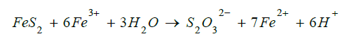
At least one method of Iron ore biomining, the thiosulfate mechanism requires 0.14 grams of water for every gram of Iron produced –which would presumably need to be extracted from a comet using a process also highly technically challenging.
Three options for the 10 km ring are modelled in TABLE 5 and 6 with associated power and materials flow requirements being the main points of interest. Hundreds of GW of power will be required presumable more likely by giant solar panels than nuclear means given today’s powers stations produce a small fraction of this output (FIG. 15).
TABLE 5. Alternative properties of 1km ring given three scenarios.
| Dimensions | Units | Option 1 | Option 2 | Option 3 |
|---|---|---|---|---|
| Outer Diameter | m | 1,000 | 1,000 | 1,000 |
| Section Outer Diameter | m | 100 | 100 | 100 |
| Inner Diameter | m | 800 | 800 | 800 |
| Wall Thickness | m | 0.5 | 2 | 0.02 |
| Additional Print Area | % | 200% | 200% | 200% |
| Internal Volume | m3 | 2,12,98,739 | 1,86,63,384 | 2,21,70,111 |
| Total Print Volume | m3 | 9,07,975 | 35,43,330 | 36,603 |
| People on Board | 5,000 | 10,000 | 20,000 | |
| Ground Floor Space | m2 | 1,25,664 | 1,25,664 | 1,25,664 |
| Average volume per person | m3 | 2,130 | 933 | 554 |
| Floor Space per person at 2.5 m ceiling | m2 | 852 | 373 | 222 |
| Total Mass of People | Ton | 310 | 620 | 1,240 |
| Manufacturing Process | ||||
| Print Speed | m/s | 0.5 | 0.5 | 0.5 |
| Nozzle Diameter | mm | 100 | 200 | 4 |
| Print Depth | mm | 20 | 40 | 2 |
| Nozzle volumetric flow rate | cm3/s | 1,000 | 4,000 | 4 |
| Number of Print Head Nozzles | 16 | 32 | 160 | |
| Print Efficiency | % | 90% | 90% | 90% |
| Number of Complete Revolutions | million | 0.1 | 0.05 | 0.1 |
| Print Time | days | 7,748 | 3,865 | 7,754 |
| Print Time | years | 21.2 | 10.6 | 21.2 |
| Material Requirements | ||||
| Main Structure Material | Moon Rock | Moon Rock | Aluminium | |
| Wall Design Density | % | 100% | 100% | 50% |
| Total Mass | Tons | 25,78,648 | 1,00,63,056 | 49,506 |
| Raw Materials Production Rate | tons | 332.8 | 2,603.30 | 6.4 |
| /day | ||||
| Falcon Heavy Lifts | 40,291 | 1,57,235 | 774 | |
| Launch Cost | $m | 150 | 150 | 150 |
| Lifts frequency | days | 0.2 | 0 | 10 |
| Lift Cost | $bn | 6,043.70 | 23,585.30 | 116 |
| Power Requirements | ||||
| Process Efficiency | % | 70% | 70% | 70% |
| Continuous Power | kW | 35,054 | 2,80,430 | 5,119 |
| Panel Efficiency | % | 40% | 40% | 40% |
| Theoretical Minimum Panel Size | m2 | 64,201 | 5,13,608 | 9,376 |
| Square Sides | m | 253 | 717 | 97 |
| Diameter | m | 286 | 809 | 109 |
| Panel Size Using ISS panel size / power ratio | m2 | 10,43,265 | 83,46,122 | 1,52,363 |
| Square Sides | m | 1,021 | 2,889 | 390 |
| Diameter | m | 1,153 | 3,261 | 441 |
TABLE 6. Alternative properties of 10 km ring given 3 scenarios.
| Dimensions | Units | Option 1 | Option 2 | Option 3 |
|---|---|---|---|---|
| Outer Diameter | m | 10000 | 10000 | 10000 |
| Section Outer Diameter | m | 1000 | 1000 | 1000 |
| Inner Diameter | m | 8000 | 8000 | 8000 |
| Wall Thickness | m | 10 | 10 | 10 |
| Internal Volume | km3 | 9 | 9 | 9 |
| Total Print Volume | km3 | 13 | 13 | 13 |
| People on Board | 1000000 | 5000000 | 10000000 | |
| Ground Floor Space | km2 | 13 | 13 | 13 |
| Average volume per person | m3 | 4365 | 873 | 436 |
| Floor Space per person at 2.5 m ceiling | m2 | 1746 | 349 | 175 |
| Total Mass of People | Ton | 62000 | 310000 | 620000 |
| Manufacturing Process | ||||
| Print Speed | m/s | 1 | 5 | 8 |
| Nozzle Diameter | mm | 2000 | 500 | 1000 |
| Print Depth | mm | 1000 | 250 | 250 |
| Nozzle volumetric flow rate | cm3/s | 2000000 | 625000 | 2000000 |
| Number of Print Head Nozzles | 250 | 500 | 100 | |
| Flow Rate per Nozzle | ton/s | 5.68 | 1.78 | 5.68 |
| Flow Rate all Nozzles | ton/s | 1420 | 888 | 568 |
| Number of Complete Revolutions | million | 0.01 | 0.07 | 0.18 |
| Print Time | years | 9.8 | 15.6 | 24.4 |
| Material Requirements | ||||
| Main Structure Material | Moon Rock | Moon Rock | Moon Rock | |
| Total Mass | Tonnes | 19137466050 | 19137466050 | 19137466050 |
| Proportion of moon [7] | % | 1.8E-09 | 1.8E-09 | 1.8E-09 |
| Raw Materials Production Rate | tonnes/day | 5375888 | 3359930 | 2150355 |
| Power Requirements | ||||
| Continuous Power | GW | 1095 | 685 | 438 |
| Theoretical Minimum Panel Size | m2 | 2006279435 | 1253924647 | 802511774 |
| Square Sides | m | 44792 | 35411 | 28329 |
| Diameter | m | 50555 | 39967 | 31974 |

Figure 15: Estimated earliest dates for start of technology availability for three habitat sizes and manufacturing rats and subsequent build timings.
Conclusion
The additive manufacturing process described can be made to work in space, there are multiple potential advantages in construction of a torus type structure in one piece using this method, largely as a result of simplicity:
• With only a small number of moving parts required in the manufacturing process the design of the production facilities should be comparatively cheap (when considered against other imagined orbital construction methods).
• The manufacturing process is suited to being automated.
• The manufacturing process is scalable.
• The structure design has fewer internal interfaces to consider making the design comparatively cheap and quick
• Design can be done in parallel with manufacture
• By building the internal services directly into the main infrastructure there is lower failure risk either through design or in service
• Basic modelling suggests a habitat capable of sustaining the human species in the event of an extinction level event is feasible this century or early into the next.
REFERENCES
- Jeff Bezos’s ambition to colonise space is straight from the 1970s.2019
- The promises and perils of space-based additive manufacturing.2014.
- International Space Station Facts and Figures. 2023.
- How big is the moon? 2022.
- The Falcon Heavy is an absurdly low-cost heavy lift rocket. 2018.
- Siddiqui MH, Kumar A, Kesari KK, et al. Biomining—a useful approach toward metal extraction. Am.Eurasian J. Agron. 2009;2(2):84-8.[Google Scholar].
- Density of Metals. 2015.
- How to Calculate Electricity Cost for Melting Metal in Induction Melting Furnace. 2013.
- Injection Molding: Melting Amorphous vs. Semi-Crystalline Plastics. 2018.