Original Article
, Volume: 6( 2)A Newtonian Logistic System for the Earth-Iss-Moon Cargo Delivery
- *Correspondence:
- Khoshyaran MM, Economics Traffic Clinic-ETC, 34 Avenue des champs Elyses, 75008 Paris, France, Tel: +32 10 47 21 11; E-mail: Megan.khoshyaran@wanadoo.fr
Received: June 05, 2017; Accepted: July 09, 2017; Published: July 15, 2017
Citation: Khoshyaran MM. A Newtonian Logistic System for the Earth-Iss-Moon Cargo Delivery. J Space Explor. 2017;6(2):125
Abstract
The objective of this paper is to introduce a new cargo logistic system for Earth-ISS-Moon cargo delivery. The new logistic system is called the Newtonian Logistic System (NLS). The Newtonian logistic system is based on a slingshot structure that uses the Newtonian forces. This paper discusses the details of the NLS. The NLS consists of at least (3) steps. Step one, consists of launching a guided cargo ( cargo guided by a booster drone) from Earth towards the lower orbit of the ISS. Step two, Once the guided cargo is in orbit it waits to be picked up by a tow drone that is slingshot apparatus which is a new structure added to the ISS for this purpose. The tow drone then brings the guided cargo to the ISS. Step three, On the ISS the cargo is unloaded and either is reloaded for delivery to the Moon, or is sent back to Earth. Both the Booster drone and the Tug drone are equipped with an special propulsion engine called Modified Linear Propulsion engine. This is a linear engine modified to work in space. The term "drone" is used in place of UAS (Unmanned Aircraft Systems) in order to imply a more idealistic vision of the aircraft.
Keywords
Newtonian logistic system; Sling structure; Booster drone, Tug drone; Guided Cargo; Modified linear engine
Introduction
This paper is a sequel to the paper entitled “A New Economic Theory for Space Exploration”, [1]. In the paper, the following idea was introduced: what if there was a way to have unlimited supply of energy. What would be the economic consequences of such a scenario. The unlimited source of supply would be provided by constructing a nuclear plant and or solar panel farms on the Moon, and then the electricity produced would be sent to Earth. The idea is not only interesting but also applicable if a practical logistic plan existed, so that the supply of material, and equipment was easily provided and there was a way to transfer this energy to the Earth. The very first step to achieving this goal is to have a functional logistic system that would allow the transfer of cargo from Earth to the ISS and to the Moon. Functional in this context means reliable, cost efficient, safe, and easy to implement logistic system. In order to build such energy producing facilities, a new logistic system is proposed in this paper.
The objective of this paper is to introduce a cargo logistic system for the Earth-ISS-Moon trajectory. The new logistic system is called the Newtonian Logistic System, (NLS). The Newtonian logistic system is based on using Newtonian forces, (F = m× a), where (F) is the Newtonian force, (m) is mass, and (a) is acceleration produced by a sling effect in order to send off a guided cargo from earth into space. On Earth, a sling structure which is an edifice much like a modified version of the Eiffel tower serves as the base of the sling. (2) Cables are attached to the tip of the structure to be used for a sling shot. A cargo pod with a drone attached to it is shot from this structure into the lower orbit of the ISS. A guided cargo pod is a cargo pod that is aided by a drone. The drone is called a booster drone. The purpose of the booster drone is to keep the acceleration and the momentum of the cargo pod stable, and maintain the cargo pod in orbit. The specifications of a booster drone are given in a later section. This guided cargo pod is then towed back to the ISS by a tug-drone already waiting on the ISS for this purpose. A new addition to the ISS is proposed that is easy to assemble and use. This addition is a sling apparatus and a support structure to hold the sling apparatus in place. From the sling apparatus on the ISS, a drone is sling shot towards the guided cargo pod. This drone is called a tug drone. The function of a tug drone is to tow the cargo pod back to the ISS. Once the tug-drone attaches itself to the guided cargo it carries the guided cargo back to the ISS. The tug-drone as well as the booster drone are a specially built drone that can move in space vacuum at a high speed required for this operation. The speed of the tug-drone is a function of the speed of the guided cargo in space, and the rotational speed of the ISS. Once anchored on the ISS, the contents of the cargo pod can then be hauled back into the ISS through a “Transport tube”. The transport tube is part of the new modification to the ISS. Both the booster drone and the tug drone are equipped with special propulsion engines. The function of propulsion engines is to keep a stable acceleration while within the Earth’s atmosphere, and maintain velocity and orbit in space. Essentially, the propulsion engine is a modified linear engine. Both the booster drone and the tug drone are equipped with (4) linear engines. The linear engines are modified to increase their efficiency, power, and endurance. They are also designed to work on and off during flights. The design and the schematics of a modified linear engine are given in a later section. A special design for a cargo pod is proposed in order to fit the cargo pod to the sling structure on Earth and on the ISS, and also to carry as much load as possible. The design, schematics of a cargo pod are given in the section on this subject. Cargo delivery to the Moon is done in a somewhat similar manner. A tug-drone can be sent off attached to a guided cargo towards the Moon using the sling shot effect. The force required is the function of the momentum and the kinetic energy of the ISS and the Earth's gravitational force. Once the cargo is dropped on a specific location on the Moon the tug drone returns back to the ISS. On Earth, the sling effect is produced using a sling structure. A sling structure is a rig type construction. A sling structure consists of an edifice much like a modified version of the Eiffel tower or a pyramid that serves as the base of the sling. Cables are attached to the tip of the structure to be used for a sling shot. A cargo pod with a drone attached to it is shot from this structure into the lower orbit of the ISS. Figure 1 depicts the sling shot structure.

Figure 1:Slingshot structure.
The drone is called a booster drone. The purpose of this drone is to keep the acceleration and the momentum of the cargo pod stable, and maintain the cargo pod in orbit. A new addition to the ISS is proposed that is easy to assemble and use. This addition is a sling apparatus adapted to the ISS structure and accommodates the guided cargo and the tug drone. From this sling structure, a drone is slingshot towards the cargo pod. This drone is called a tug drone. The function of the tug drone is to tow the cargo pod back to the ISS. The same tug drone can be sling shot from the ISS towards the Moon as well. The contents of the cargo pod can then be hauled back into the ISS through a “Transport tube”. Transport tube is part of the new modification to the ISS. Both the booster drone and the tug drone are equipped with (4) linear engines. Figure 2 depicts the process of a guided cargo being towed back to the ISS.

Figure 2: Depiction of a tug drone towing a guided cargo back to the ISS.
The current logistic models are divided into (2) major categories: 1) Scheduling models, and 2) Technological advancement models. The scheduling models are those logistic systems that mainly focus on task ordering and task sequencing optimizati [2-10]. Technological advancement models are logistic systems that focus on technical improvements. These models deal mainly with how to optimize the use of the existing technologies, [11-20]. The Newtonian Logistic System falls into a new category of logistic models. In the proposed NLS, the focus is on the design of a structure to replace the current mode of access to the ISS and eventually to the Moon, rely on methods that are based on Newtonian forces such as Work, and Kinetic energy, and find mechanical solutions that can be applied easily, and in case of problems can be repaired manually. Section (2) provides a detailed description of the sling structure on Earth. Section (3) gives a detailed description of the design and the schematics of the modifications required to the ISS for a sling structure, and a full discussion of the functionality of such modifications. Section (4) gives a thorough discussion on space drones including the design and the schematics of such drones, in particular, the booster drones and the tug drones. Section (5) provides a technical discussion on modified linear engines. In particular, the design, the schematics and other technical details are discussed. Section (6), introduces the design and the schematics for a sling shot adapted cargo pod. Section (7) gives details of the design details of sling cables both for the sling structure on Earth, and on the ISS. The paper ends with some concluding remarks.
Sling Structure
The sling structure has (3) levels. Figure 3 provides an overview of the sling structure on Earth. The structure resembles a sort of a pyramid. In its general aspect, it is similar in structure to the Eiffel tower. However, several modifications distinguish this structure from the Eiffel tower. Unlike the (2) beams of the third level that converge at the apex, the long beams are split to allow for a sling action. There are (3) platforms in place of the (2) platforms of the Eiffel tower. As is shown in Figure 3 there is a column in the centre of the structure to allow for higher stability and better accessibility. One major difference is the height of the structure. The Eiffel tower is 300 meters in height. The sling structure has a totally different dimension. Level one is 10 km in height. Level (2) is 40 Km in height, and level (3) is 30 km in height. This makes for a structure of 80 km in height. One major issue is accessibility to all (3) levels. At least (2) of the (4) level one and two beams are equipped with fast tracks for bullet shuttles used to carry engineers and maintenance crew up to level (1), and (2). The other (2) beams are equipped with a pulley that moves a wagon up and down to levels (2), and (3). This wagon can be used to send equipment, construction and maintenance materials to the upper levels, plus counteract the vibration and torsion forces caused by the movement of the bullet shuttles. Due to the steep angle of the 2 split beams of level 3, access to this level is secured by a pulley system only. Both branches of level (3) are equipped with pulley and wagon systems. The center column is equipped with a fast elevator. This elevator provides access to the platforms on levels (2), and (3). The function of this elevator is to provide fast access to the platforms only.

Figure 3:An overview of the sling structure on Earth.
Level 1
Figure 4 gives more detailed schematics of level (1). Level 1, is the base of the pyramid like sling structure. It is made up of 4 large beams anchored to a solid foundation. These beams have to withstand not only the weight of the other 2 levels, but also the bullet shuttles and the wagon carrying pulleys. In general, forces acting on level (1) beams and the foundations holding the beams in place are: axial forces such as tension and pressure due to bullet shuttle and pulley cables displacement. Other forces acting on this level are torsion, shear, and compression forces due to cable's and the guided cargo pod's weights and sling action. Somewhat less important factor to consider is wind, storm, and other climate fluctuations. The area covered by level (1), is about 8400 m2. The height of level (1) is 10 Km. The (4) beams are made of re-enforced cast iron exposed latticework. This design allows for the installation of fast tracks for the bullet shuttles, and wagon carrying pulleys, plus reduces the weight of the structure. The curve and the angle of inclination of the 4 beams should be calculated in such a way that would optimize the resistance to the forces mentioned above. At 10 Km, a platform holds the 4 beams of the level 1 together. The platform is made of re-enforced cast iron. The area of level (1) platform is half the area of the base, about 4200 m2. Each of the (4) foundations must be of re-enforced concrete. The width and the depth of each foundation are determined based on the geological characteristics of the ground, and in consideration with the forces acting on the level 1 structure. The central beam contributes both to the stability of the base structure, and provides an additional access to the upper levels since it is equipped with a fast-moving elevator. The central beam is made of re-enforced cast iron. Figure 5 demonstrates an example of one type of a bullet shuttle, in particular Maglev type shuttle, [21]. Figure 6 demonstrates an example of a fast-moving elevator [21].

Figure 4:Schematics of level (1).

Figure 5: Maglev type shuttle.

Figure 6:Example of a fast elevator.
Level 2
Figure 7 provides the schematics of level 2. The structure of level (2) is similar to level (1). There are 4 beams. Each beam is a re-enforced cast iron latticework. The height of level 2 is 40 Km. Level 2 is 3 times higher than level 1. Level (2) extends to the stratosphere layer of the Earth. A metal lattice platform holds the (4) beams together. The middle column is extended to level 2, and is equipped with an elevator. To further stabilize the structure, one could eventually consider support rods to connect the beams to the middle columns. For construction and maintenance purposes, (2) out of the (4) beams are equipped with bullet shuttles that run along the 40 km length. Given that there is temperature variation between the lower and the upper part of level (2), the bullet shuttle cannot function exactly the same way as in level (1). The upper level is significantly warmer than the lower level due to absorption of sunlight by the ozone. Both the shuttles and the center column elevator should be pressurized and tracks and elevator cables should be protected from high temperature of this level. The pulley system of the other (2) beams should be isolated in order to resist high temperatures. In general, the whole structure of level 2 should be protected against high temperature, and corroding due to possible ionization. Level (2) is most impacted by the movement of the (2) shuttles and the (2) pulleys that cause vibration, and Newtonian forces such as torsion, compression and shear forces. Other Newtonian forces acting on this level are the tension and pressure due to the sling action, the sling cable movement, and the weights of the cargo and the booster drone.

Figure 7: Schematics of level (2).
Level 3
Level (3) is 30 km high. At this height, the structure is in the Mesosphere. In the mesosphere temperatures drop with increasing altitude to the mesopause at the top of this layer. This layer is the coldest and has an average temperature around (-85°C). Figure 8 provides the schematics of level 3. This level consists of 4 beams made of fortified cast iron lattice structure. Two beams are attached on either side, so that it forks out. This is done to provide a basic Y-shaped frame. A metal lattice platform holds the Y-shaped frame together. Two pegs are attached to each branch of the Y-shaped frame on the platform. A cable is attached to each peg. The middle column is extended to level 3, and is equipped with an elevator. Support rods connect the Y-shaped frame to the middle column. For construction and maintenance purposes, the support rods are designed as staircases that connect the Y-shaped frame to the middle column. Provisions must be made to enhance the top level of the sling structure. An isolation coating is needed to preserve the fortified cast iron lattice work. Attention should be paid to noctilucent clouds, sprites or ELVES that occasionally form in this layer above Tropospheric thunderclouds, and finally occasional meteors. Due to the steep angle of the Y-shaped frame of the third level, and atmospheric problems mentioned earlier, at this level only a pulley system can operate safely.

Figure 8: Schematics of level (3).
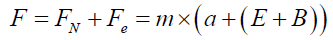
At level (3), the Newtonian forces at work are torsion and shear forces due to pulley operation, and tension and pressure forces due to sling action. Figure 9 shows a diagram of Newtonian forces acting on the entire sling structure. To reduce the impact of a sling action on level (3), and help improve the force of the sling, it is proposed to enhance the sling action or in other words maximize the draw length. In order to achieve a maximum stretch capacity of the sling cord must create a confined electromagnetic field around the sling at the launch pad level, where the sling cords are attached to the guided cargo pod's launching gear. The electromagnetic field renders an extra force to the sling. Total force required to sling shot the cargo into space (F) is given as:

Figure 9: Diagram of Newtonian forces.
 (1)
(1)
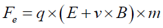
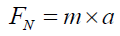
(FN) , is the Newtonian force, function of mass (m) and acceleration (a). (Fe) , is the electromagnetic force, function of electric field (E), electromagnetic field, (B), mass (m), required electric charge (q), and required velocity (v). Given the mass of the cargo pod and the booster drone, and the distance from Earth to the low ISS orbit, the required total force (F) can be calculated. The sling shot action should be designed in a way that the action would carry the cargo through the Thermosphere, i.e. over 120 km above Earth. The velocity (v), and the acceleration (a) required for the sling shot is determined through the set of Equations (1).
The sling structure is a feasible structure due to its' design (fork shaped pyramid) which renders such a structure lighter than other possible designs. The second element that allows for reduction is weight is that the bulk of the weight of the structure is supported by level one, therefore, it is of utmost importance that the four foundations are planted deep in the ground and the beams are appropriately separated from each other. The base area of the sling structure is an important element that should be precisely calculated. A possible area width is suggested in the description of the level one section. The tension and pressure applied to the structure by the sling action is reduced since the launch base of the sling is enhanced by confined electromagnetic field which provides extra stretch for the sling cables, but reduces the tension on the third level beams. Last important element in the central column which is connected to the sling structure through side beams. The central column reduces the weight of the structure since the forces applied to the structure are distributed between the structure and the central column.
Modification to the ISS: A Sling Apparatus
Modifications required to the ISS are minimal. It is required to install a sling type apparatus on the ISS, which can be done with a minimum amount of equipment and effort. The purpose of a sling structure is to send off a tug drone to tow the guided cargo back to the ISS, but also eventually sling shot the guided cargo either back to Earth or to the Moon. A tug drone can be sling shot to the Moon from the ISS separately. Figure 10 provides the schematics of the ISS modifications required for a sling apparatus.

Figure 10: Overview of the ISS required modifications.
As is shown on the schematics of the required modifications (2) platforms are needed. The upper platform is needed to attach the sling cables, and the lower platform is required to hold a launch pad and a sling apparatus. Support and safety beams stabilize levels (1) and (2) platforms. A transport tube is attached to the Progress cargo module and is extended to level (2) platform where it opens to provide access to the guided cargo pod’s hatch. Level (1) platform is equipped with (2) pegs designed to hold the sling cords. Level (2) platform is equipped with a sling apparatus. Cargo and the booster drone to attach to the sling apparatus. The cargo hatch can be reached from the transport tube and it is through this opening that cargo can be hulled up through the tube to the Progress cargo module. While the cargo is on the level (2) platform, the tug drone is also attached to the sling apparatus. A guided cargo can be sent off to the Moon using the sling shot structure of the ISS. Figure 11 shows the required modifications.

Figure 11: Schematics of the ISS required modifications.
The first platform is similar in form to the solar panels on the ISS in a way that it should be light and be made of a light metal alloy. Platform (1) has 3 attachments: 1. A metal frame is attached to this platform, 2. A transport tube passes through this platform, 3. Sling cords are attached to metal pegs installed on platform (1), as is shown in Figure 12. The transport tube is equipped with a pulley to help haul cargo into the ISS. The transport tube is also equipped with handle bars to help astronauts move easier along the length of the tube. Two pegs are installed on either side of the transport tube. The pegs are to attach the cables of the sling apparatus. The transport tube is stabilized by two metal support rods that extend from the ISS to the lower platform.

Figure 12: Platform (1).
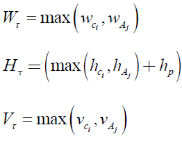
The second platform is similar in structure and shape to platform (1). Platform (2) has the following attachments: 1. A landing/ launching pad for the cargo pod and the booster drone. 2. Transport tube opening that would allow for astronauts to exit the tube and access the cargo pod hatch, also to carry cargo into the transport tube and attach it to the pulley to be hauled back into the ISS. The width, (Wt), height, (Ht), and the volume, (Vτ ) the transport tube are defined as in the set of Equations (2).
 (2)
(2)
The width of the transport tube is the maximum between the width of the largest cargo, 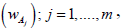 where (n) is the number of cargo items, and the widest astronaut, where (m) is the number of astronauts. The same goes for the height, (H ) τ , which is the maximum between the height of a cargo piece,
  and the height of an astronaut,
 to this must add the height of the pulley,
  . The volume of the transport tube is calculated the same way as the width. This implies that the volume of the transport tube is the maximum between the volume of a cargo item, and the volume of an astronaut,
 . The sling frame is installed on the lower platform. This frame consists of a metal mound with an extension. This extension is a special beam in the form of a metal spring attached to the sling mound. The tip of the spring is equipped with a device that attaches itself to a guided cargo pod or a tug drone while spring is compressed and opens to slingshot a drone or a guided cargo pod when the spring is released. The schematics of the sling apparatus are shown in Figure 13a, and 13b. Figure 13a, provides a detailed visual description of the sling apparatus. The sling apparatus consists of the following pieces: 1) a vertical metal stand, 2) a horizontal spring, 3) (2) metal bars attached to the metal stand of sling apparatus. Their function is to provide a Y-frame for the slingshot and an anchor for the tug drone. An idle tug drone can hook onto one of the Y-frame bars. 4) The spring is equipped with a special tip designed to attach itself to a guided cargo, and a segment of the sling cable is used as a pad for launching either a guided cargo or a tug drone. As is shown in Figure 13b, the opening of the transport tube is near the hatch door of a cargo pod so that the cargo can be downloaded and send off by attaching the cargo to the pulley of the transport tube. The guided cargo pod (cargo, and the booster drone) at this stage is anchored to the spring extension of the sling frame. The tug drone that hauled the guided cargo back to the ISS is also anchored to the same spring extension of the sling frame. Figure 14 shows the process of a tug drone towing a guided cargo in space. As is shown in Figure 14, the tug drone attaches itself to the guided cargo pod. The attachment is done using (2) elements. There is an extension rod attached to the guided cargo pod. The tug drone is equipped with a mechanical arm that hooks onto the extension rod. The tug drone tows the guided cargo back to the ISS lower platform. The booster drone and the tug drone work together by adjusting velocity and acceleration. The process is shown in Figure 15. A tug drone can be sling shot from the ISS towards the Moon with a guided cargo pod in tow and back. A similar to the ISS sling apparatus should be built on the Moon. This way the tug drone and or the guided cargo pod can be sling shot from the Moon towards the ISS. The back and forth trajectory of a tug drone and a guided cargo is shown in Figure 16.

Figure 13a: Schematics of a sling apparatus on the ISS.

Figure 13b: General Schematics of a sling apparatus on the ISS.

Figure 14: A guided cargo in tow by a tug drone.

Figure 15: 2 drones interaction in space.

Figure 16: ISS–Moon trajectory.
Drones
Booster drone
For the proposed NLS, 2 types of drones are required. One type of a drone needed is a booster drone. The function of this drone is to help maintain acceleration and momentum of a cargo pod during its' trajectory and while in orbit. In addition, it maintains the angle and the trajectory set by the sling shot. One possible design of a booster drone is shown in Figure 17. This design consists of a mainframe in a rectangular shape with hollow supports and hooks. The cargo pod rests on these hollow supports. The hooks are fastened to the cargo pod to secure and maintain it in position during the flight. A booster drone is equipped with (4) engines which are attached to each corner of the rectangular frame. The function of these engines is: to provide propulsion, maintain momentum, and be capable of orbit stabilizing action. Propulsion action starts at the point of the entry to the Thermosphere, just before entering space. Momentum and orbit stabilizing functions start once the cargo pod is in orbit. The (4) engines keep the cargo pod on the lower orbit of the ISS and maintain a suitable speed while waiting to be towed back to the ISS by a tug drone. Figure 17 depicts a cargo pod attached to a booster drone with (4) engines.

Figure 17:Booster drone design.
For the (4) booster engines the following elements are important: 1) shape of the engines, 2) size of the engines, 3) type of energy source used, 4) compatibility with a drone structure, 5) effectiveness in the sense that they should do the job efficiently, 6) energy consumption level, 7) endurance, meaning the length of the time engine is in use, and the frequency of use, and finally, 8) accessibility to the materials needed for repair and replacement. The booster drone design depicted earlier does not represent the actual proportions between the cargo pod and the booster drone. The size of the booster drone should be about of the size of the cargo pod. The cargo pod imagined in this paper would be about the size of a compact car, let’s say about (3.4 m) long, (1.48 m) wide, and (2 m) high. This could increase to (4.7 m) long, (1.7 m) wide, and (2 m) high, the dimensions of a normal size car. The size of the drone should be about (0.8 m) long, and (0.37 m) wide. The height is adjusted to accommodate the (4) booster engines. The booster drone is equipped with an extension or anchor rod. The tip of the anchor rod is attached to a hollow ball. The hollow ball is not the only possible design. A hook can also be used for the anchoring purpose. Other attachment designs could be explored. The hollow ball is for the tug drone to attach itself to the cargo pod and tow it back to the ISS’s newly constructed 2nd platform with a launch pad. A booster drone with an extension rod is shown in Figure 18. Booster drone maintains the angle and the trajectory set by the sling shot.

Figure 18: Booster drone with an extension rod design.
Tug drone
The function of a tug drone is to tow the guided cargo pod (cargo pod maintained on the lower orbit by a booster drone) from the lower ISS orbit to the ISS. The design of a tug drone is different from the design of a booster drone. A tug drone has an elongated shape very much like a rocket. On either side of a tug drone a modified linear propulsion engine is attached. The modified linear propulsion engine is the same used for a booster drone. Tug drones are equipped with towing gears. The towing gear is designed is such a way that allows a tug drone to attach itself to a guided cargo. The towing gear consists of a mechanical arm with a grip stored in the tail of a tug drone as is shown in Figure 19. The towing action can be done in (2) ways: 1. The tug drone’s automatic arm attaches itself to the hollow ball of the extension rod. 2. Extension rod is equipped with a hook: the tug drone has to make several maneuvers to anchor the wings to the hook. These maneuvers are: a) steer behind the hook in a way that the wings are behind the hook, b) elevate the tug drone, c) move forward to let the wings be trapped behind the hook. Tug drone is equipped with 2 engines that can accelerate or slowdown in space with little loss of time or energy. The acceleration is helped using a slingshot action performed from the lower platform of the ISS. Tug drone is equipped with an engine especially designed to function in space. One possible engine type to be used for both the booster drone and the tug drone is a modified linear motor. Figure 20 shows a tug drone design with different types of towing possibilities.

Figure 19A: Tug drone design with an automatic arm.

Figure 19B:Tug drone design with an automatic arm attached to a cargo pod.

Figure 20: Tug drone design without an automatic arm.
It should be noted that the problem of changing orbit is solved by the use of (2) types of drones: the booster drone, and the tug drone. The booster drone is guided from Earth, and the tug drone is guided from the ISS. Any random trajectory deviations are corrected. The problem of Lower Earth Orbit is solved since with the help of the booster drone, cargo pod is maintained in the lower orbit of the ISS, waiting to be towed back to the ISS. The use of drones with modified linear engines allows for continuous trajectory corrections, more flexible maneuvering, and more powerful propulsion capacity.
Modified Linear Engine
A modified linear propulsion engine has the following pieces: 1) A fixed magnet, 2) 2 rows of thick layers of coils, 3) 2 sets of metal springs, 4) a piston, 5) a combustion chamber, 6) a spark plug, 7) a gas injector, 8) a condensed Hydrogen Peroxide gas tank, 9) a combustion nozzle, and 10) a small solar panel. Figure 21, 22, 23a, 23b, show different aspects of a modified linear propulsion engine. Figure 21 depicts a linear motor. The new addition is (2) dense metal spring coils that are added to the piston bed. The purpose of these springs is to accelerate the movement of the piston. Figure 22 depicts additional attachments required to convert a linear motor into a propulsion engine. Additional attachments are:

Figure 21: Modified linear engine, part 1.

Figure 22:Modified linear engine, part 2.

Figure 23a: Modified linear engine, part 3.

Figure 23b:Modified linear engine, part 4.
• A combustion chamber with a sensor equipped lid,
• A gas tank,
• A gas injector,
• A spark plug,
• A solar panel, and
• A combustion nozzle.
Figure 23a shows a propulsion engine which consists of a linear motor with all the additional attachments. Figure 23b shows a new fueling system which consists of adding the following pieces:
• A hot air balloon to collect the hot air of the blast that comes out of the combustion nozzle.
• A pipe that connects the hot air balloon to the gas tank. This pipe is lined with monopole magnets on one side, and Ferrous (Fe2+), and Titanium (III) Chloride, (Ti3+) on the other side.
• The gas tank contains condensed Hydrogen Peroxide (H2O2).
A new fueling process is proposed for the modified linear propulsion engine. The schematics of the new fueling system is shown in Figure 23b. The hot air blast that comes out of the combustion nozzle is collected in what is called a hot air balloon. At this point the Hydrogen Peroxide (H2O2) is decomposed into water ((H2O), and oxygen (O). Both water and oxygen go through the quantum level modification pipe. The walls of the quantum level modification pipe are lined with strong magnetic monopoles on one side, and Ferrous (Fe2+), and Titanium (III) Chloride, (Ti3+) on the other side. Once water and oxygen pass through the pipe, they get decomposed into Hydroxyl radicals (HO), and Hydroperoxyl radicals (HOO) due to the presence of (Fe2+), and (Ti3+). Once decomposed, strong magnetic monopoles keep the electrons of each of the existing atoms on the highest spin level. Once the atoms are given an energy boost, they are cooled off so that they become Hydrogen Peroxide (H2O2), molecules again. At this point each molecule of the now cooled off Hydrogen Peroxide (H2O2) is at the highest energy level. When sparked it produces more mechanical energy, and therefore stronger blast force. The process of ionization and radicalization of Hydrogen Peroxide (H2O2) is repeated as long as it is possible to keep the spin at its highest level. The strength of the modified linear motor depends on the volume of the gas tank. The modified linear propulsion engine can be turned on and off as often as is needed. A booster drone can work for as long as it is required. There is no time limit to the use of the booster drone since the fuel as is described is only limited by volume.
The hot air blast that is collected in the hot air balloon (Figure 23b), does not reduce the thrust power of the engine and thus does not affect the momentum produced by the blast. There are two reasons for this. The blasted Hydrogen Peroxide (H2O2) is decomposed into unstable radicals Hydroxyl radicals (HO), and Hydroperoxyl radicals (HOO) that are much lighter than the cold concentrated (H2O2). Once these light radicals hit the wall of the hot air balloon, they lose their velocity significantly. As their velocity slows down they are vacuumed through the quantum level modification pipe. This process is not different from releasing the blast into space. The drone's momentum is not affected, since the thrust is not impacted. Another significant fact is the nature of fueling of this engine. Unlike gasoline, the use of Hydrogen Peroxide (H2O2) allows for quantum level manipulation. This implies that the pipe is designed to change the energy level of the atoms by creating radiant electrons before cooling off the atoms and their re-attachment to become higher energy level Hydrogen Peroxide (H2O2) molecules. The consecutive blast is much stronger than the initial one, which implies much higher thrust and thus momentum. The quantum manipulation technique allows for a continuous powerful blast each time.
Cargo Pod Design and Safety Issues
In general, the following characteristics are desirable in the design of a cargo pod: 1) Cargo pod must be made of a light material, and 2) the shape of the cargo pod must be aerodynamic. The most adapted aerodynamic shape for a sling mechanism is a sphere, but other design such as a cone shaped cargo pod could be used as well. 3) Cargo pod must be heat and radiation resistant, 4) the size of the cargo pod should be approximately the size of a small compact or a medium size car. This is appropriate for loads such as food, laboratory instruments, replacement materials, etc. For heavier items additional considerations are required. Safety attachments are required such as a special parachute to be used in case of accidental drop of the cargo pod. (2) types of cargo pod designs are proposed here. A spherical cargo pod is one possible design option. In this design, the wall of the cargo pod is equipped with padded shelves. The sphere has one main hatch door that allows access to the items inside. Honey comb spherical cargo pod is another possible design option. This cargo pod design is hollow inside. The surface contains padded pockets or honey combs that can be accessed from the surface of the honey comb sphere. In this design, each honey comb has its own individual hatch door. The third design option is a cone shaped cargo pod. In this design, the walls are equipped with padded shelves. This design has the advantage that it is aerodynamically more adapted to a slingshot action. All cargo pods are equipped with an attachment piece to be used to attach a guided cargo to the sling apparatus on the ISS. Figure 24, 25, 26, show the three types of cargo design. The kinematics of the cargo pod with respect to the booster drone is an important element. This mainly refers to a torque force which is a force due to rotation caused by a force acting on a cargo pod. The cargo pod is liable to rotation due to torque acting on it by the Earth’s gravitational force. This can cause loss of velocity and acceleration. This problem can be corrected using a booster drone. The force acting on the cargo pod by the booster drone corrects this problem. The angle and the trajectory of the cargo pod during the exit and the entry from Earth is another important issue. This issue is addressed using the sling structure. The trajectory and the angle of exit is dictated by the slingshot.

Figure 24:Spherical cargo pod design.

Figure 25: Honey comb spherical cargo pod design.

Figure 26:Cone cargo pod design.
Sling Cable
Cables for the sling structure have the following characteristics. The length of the cables should be decided on with respect to both the normal length (cable with no tension), and the stretched length. Thickness is another factor that defines the cables for a sling structure. The cable must be thick enough to withstand the weight of the cargo pod which is about the size of a compact or medium car, with a load inside. To this must add the weight of the booster drone as well. The material of the cables is another important factor. Cables must be able to stretch, retract, and be able to support a significant load. In addition, they need insulation against extreme cold and heat. Cables made of steel and spider silk have high elasticity. A carbon nano tube cable that has a larger elasticity might be a better choice. The choice of material should be carefully investigated. The sling cables must be easy to maintain. Cables of the sling structure can be maintained by equipped workers with parachutes and other safety gears who can climb the cables to perform maintenance tasks. It is important to determine the following parameters before calculating the length of the sling cable. The length of the cable is the determinant factor in calculating the distance of the cargo pod from the base of the sling structure. These parameters are:
• Elasticity calculation using the Hooks law that says that the length of a material changes linearly when applied tension.
• Stress and strain calculations using the Young's modulus (Y), where (Y), represents both stress, and strain,
Static elongation, (s), given by the ratio,  where (L0) , is extended length of a cable, (L0) is the length of the cable without tension.
Tensile strength (T), given by the expression,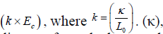 is a spring constant. In Figure 27, (x) represents the distance from the base of the sling structure. (y) is the distance from the base to the top of the structure, which is 80 km.

Figure 27: Cable length calculation.
Conclusion
The proposed Newtonian Logistic System allows for an efficient, practical, cost effective, safe, and easily applicable improvements. The system is designed to take advantage of Newtonian forces in the form of a slingshot structure to send cargo off to the ISS and eventually to the Moon. Two designs are introduced. A sling shot structure for Earth is proposed. Modifications to the ISS are proposed in order to install a slingshot apparatus for the ISS. It is proposed that special drones should be employed to help with cargo transport. Both the booster drone that is used to guide the cargo pod, and the tug drone that is used to tow the guided cargo back to the ISS are equipped with modified linear propulsion engines. The modified linear propulsion engine is designed in such a way that it can function in space. It can be turned off and back on again during the trajectory of the cargo pod, and it has a new fueling system that allows it to work for long periods of time. The general idea behind all the new designs proposed in this paper is to use technologies that are easily manageable by an individual. This means that mechanical systems are privileged over computerized systems. For the Newtonian logistic system, design is based on optimizing and smarting manual work. Optimization is equivalent to efficiency. Smart manual work is work that is well thought of and analyzed. The implications of implementing and running such a logistic system are beyond imagination. Significant improvements in the everyday life of each human, and in the advancement of societies in general are only two of the many advantages that such a logistic system could bring about.
References
- Khoshyaran MM. A new economic theory for space exploration. British Journal of Economics, Management, & Trade. 2016;2(2):1-11.
- Jones R, Kennedy K, Howard R, et al. Cislunar habitat internal architecture design criteria. Human Research Program Investigator’s Workshop, Galveston, TX. USA ; 2017.
- Keutzer K, Newton A, Rabaey J, et al. System-level design: Orthogonalization of concerns and platform-based design. IEEE Trans Comput Aided Design Integr Circuits Syst. 2000;19:1523-43.
- Ferrandi F, Lanzi PL, Pilato C, et al. Ant colony heuristic for mapping and scheduling tasks and communications on heterogeneous embedded systems. IEEE Trans Comput Aided Design Integr Circuits Syst. 2010;29(6):911-24.
- Wang G, Gong W, DeRenzi B, et al. Ant colony optimizations for resource and timing constrained operation scheduling. IEEE Trans Comput Aided Design Integr Circuits Syst. 2007;26(6):1010-29.
- Deb K, Pratap A, Agarwal S, et al. A fast and elitist multi objective genetic algorithm: NSGA-II. IEEE Trans Comput Aided Design Integr Circuits Syst. 2002;6(2):182-97.
- Pelikan M, Sastry K. Fitness inheritance in the bayesian optimization algorithm. Genetic and Evolutionary Computation Conference. 2004;3103:48-59.
- Clement BJ, Johnston MD. Design of a deep space network scheduling application, international workshop on planning and scheduling for space (IWPSS-06). Space Telescope Science Institute, Baltimore; 2006.
- Johnston MD, Giuliano M. Multi-objective scheduling for the cluster II constellation, 6th International Workshop on Planning and Scheduling in Space (IWPSS), Darmstadt, Germany; 2011.
- Chien S, Rabideau G, Knight R, et al. ASPEN-automating space mission operations using automated planning and scheduling. SpaceOps 2000, Toulouse, France; 2000.
- Broyan JL, Schlesinger T, Ewert MK. Exploration mission benefits from logistics reduction technologies. 46th International Conference on Environmental Systems, Vienna, Austria; 2016.
- Dongming Z, Miller R. Thermal and environmental barrier coatings for advanced propulsion engine systems. NASA Publication TM-2004-213129; 2010.
- Moravec HP. A Non-synchronous orbital skyhook. The Journal of the Astronautical Sciences. 1997;25(4):307-22.
- Froning HD. Combining MHD air breathing and aneutronic fusion for aerospace plane power and propulsion. 14th AIAA/AHI Space Planes and Hypersonic Systems and Technologies Conference, Canberra, Australia. 2006;6-9.
- McLaren R, Ragheb M. Nuclear propulsion choices for space exploration. 1st International Nuclear and Renewable Energy Conference, Amman, Jordan. 2010;21-24.
- Tidman DA. Sling launch of a mass using superconducting levitation. IEEE Trans Magnetics. 1996;32:240-47.
- Basnet S, Magee CL. Modeling of technological performance trends using design theory. Design Science. 2016;2(8).
- Nagy B, Farmer JD, Bui QM, et al. Statistical basis for predicting technological progress. PLOS One. 2013;8:2.
- Sole RV, Amor DR, Valverde S. On singularities in combination-driven models of technological innovation. Physics and Society. 2014;1407:6890.
- Denning PJ, Lewis TG. Exponential laws of computing growth. Communications of the ACM. 2017;60(1):54-72.
- Smitherman DV. An advanced earth-space infrastructure for the new millennium. Workshop on Geostationary Orbiting TRether” Space Elevator” Concepts, NASA Marshall Space Flight Center, Marshall Space Flight Center, Huntsville, Alabama; 1999;8-10.