Original Article
, Volume: 5( 4)Design, Construction and Optimization of Tesla Coil
- *Correspondence:
- El-Aragi GM Plasma Physics and Nuclear Fusion Department, Nuclear Research Center, Cairo, Egypt, Tel: +972 1-800-660-660; E-mail: elaragi@gmail.com
Received Date: September 23, 2017 Accepted Date: October 31, 2017 Published Date: Novmber 02, 2017
Citation: El-Aragi GM. Design, Construction and Optimization of Tesla Coil. J Phys Astron. 2017;5(4):123
Abstract
Tesla coil was proposed by an inventor Nicholas Tesla in around 1891 and known as resonant transformer or Tesla transformer (TT). Tesla transformer can produce high AC voltages at high frequency and low currents. This paper describes design and operation homemade tesla coil. Different tests were done to find the optimum conditions of operating Tesla coil such as maximum output voltage, current and spark length. Fast Fourier transformer (FFT) of primary and secondary side signals was done.
Keywords
Tesla coil; High frequency; Resonant transformer; Fast Fourier transformer
Introduction
Tesla coil is known as AC high voltage air-cored resonant transformer [1-3]. It can produce high voltage and high frequency alternating current. A Tesla transformer has several components. The primary transformer, which is input high-voltage transformer, the tank capacitor, which is a high-voltage capacitor, the spark gap and the primary coil consisting of several turns of thick heavy gauge wire wound around the base of the primary coil. In addition to the secondary coil, it consists of many hundreds of turns of relatively thin, small gauge enameled wire. The two coils make up an air-core transformer, in other words there is no iron core inside of the coils. The high-voltage sparks radiate in all directions from the top load out into the air. Coupling coefficient values of 0.6 are often employed [4-6]. A tightly coupled Tesla transformer will generate a higher average power whereas a loosely coupled Tesla transformer design will provide a higher output voltage at the expense of lower power transfer efficiency [7,8]. Small Tesla transformer is used as a gas leak detector in vacuum systems, as well as gas ionization and so on [9,10].
Experimental
Figure 1 shows schematic diagram of the construction details of Tesla coil. Usually the primary is wound at the bottom of the coil. The primary and secondary have something like 1 cm-5 cm space between them to avoid arcing from the secondary coil to the primary one. The primary should be made of few turns (3-12) of heavy wire or even copper tube or any other highly conductive material. The secondary is a large single layer coil. It should be constructed on some non-conducting material, such as PVC pipe. Winding must be neat and tight. Any overlapping will affect performance drastically.

Figure 1: (A). Schematic diagram of the construction details of Tesla coil (B) Shows photo of whole Tesla coil unit.
After secondary has been changed winded it should be insulated properly. One could use something like plastic spray, silicon, paraffin wax and many other good insulators for that. One could use something like observe any appearing corona on the coil and insulate it more or the coil will be destroyed. Arcing can be reduced between primary and secondary coils by putting a plastic tube between of them. Secondary have length/diameter of approximately four.
The high input voltage, low-frequency power source is to charge the primary tank circuit. This energy is used to charge capacitor of the primary circuit and all the energy stored in it will be transferred to the primary coil. The process of charging primary capacitor and firing the spark gap occurs rapidly. The radio frequency chokes (RFC) inductors are shown in Figure 1 act as high impedances to prevent the AC source from interfering with the oscillating primary tank circuit.
Results and Discussion
Different tests were done to find the maximum range, voltage and current outputs, spark lengths etc. The first experiment was to check the output range of the device with the variation of input voltage. For this experiment, the variable voltage source is kept at a constant voltage and then the fluorescent lamp is brought near the secondary coil (Figure 1B). As the light is brought near it starts to glow. Thus starting from zero distance it is moved farther away parallel to the ground. The results indicate that the relation between the areas of the field is directly proportional to the input voltage. The electric field is so intense near a Tesla coil that the field itself can induce movement of electrons in the rarefied gas inside the fluorescent lamp, the gas lights up and no electricity flowing through the lamp. For measuring the length of sparks that are being released, the experiment was carried out with a piece of metal object is taken near to the secondary coil (Figure 2). This would cause a sudden path for the electrons from the top load and a discharge would appear. As the sparks, slowly move the metal object away from the open end of the coil. The spark would extend to its maximum limit and not appear after the critical length. Any measuring scale can be used to detect the length of the spark. Number of turns in the coils, input voltage both of these factors is a vast scale responsible for the length of spark discharge.

Figure 2: Indicate method of measuring high voltage by spark length.
It can't simply connect a voltmeter to the tip of a Tesla coil and measure it. In this case, it must be use spark length to estimate the output voltage. Start with the scope probe a long distance away-say 20 cm. Bring it closer until see a signal. Most scopes are sensitive enough to pick up the oscillations from a Tesla coil with no antenna at all. Figure 2 shows the method of measuring high voltage by spark length, the left photo indicate the probe position from the output terminal of tesla coil and the right photo shows the spark length during operation of Tesla coil.
Figure 3 shows high voltage oscillogram using oscilloscope probe is attached to a meter of wire and dangled about one meter from secondary coil.

Figure 3: The oscillogram of measuring high voltage.
The localized partial discharge has been observed at the sharp edge of the conductor (Figure 4). Corona a type of partial discharge is the premature breakdown consists of audible and luminous effect. Energy is transferred from the primary tank circuit to the secondary circuit. The amplitude of the oscillations in primary will gradually decrease while those of the secondary will amplify. This energy transfer is done through magnetic induction. The decay of the primary oscillation is called "Primary Ring-down" (Figure 5A) and the start of the secondary oscillation is called "Secondary Ring-up" (Figure 5B). The output voltage is increased until the air near to the top terminal of secondary coil ionizes and produces corona discharge.

Figure 4: Corona (left) and glowing a fluorescent light wirelessly (right).

Figure 5: (A) Primary Ring down and (B) Secondary Ring up.
To investigate actual tuning ratio in the circuit, Fast Fourier transformer FFT of primary and secondary side signals were done. As shown in Figure 5, 6 and 7, FFT spectrums indicate that slight mismatch in the tuning does exist, which could be due to ground coupling capacitance.

Figure 6: FFT Spectrum of primary signal.

Figure 7: FFT Spectrum of secondary signal.
The power and integral energy of the primary coil is shown in Figure 8.

Figure 8: Typical power and integral energy waveforms.
Once the ionized air channel is formed the air is constantly super-heated by the discharge. The plasma in the discharge is very hot and lowers the voltage required to maintain the discharge. The spark may appear to grow if a director is used. It takes approximately 10 kV to ionize every inch of air in a spark gap coil. The calculated secondary voltage will produce a spark
length of: 
Where:
SL=Length of high-voltage discharge (spark) in inches.
Vs=Peak voltage in the secondary winding.
An alternate formula for calculating the average power in the secondary:
Where:
Cs=Self-capacitance of secondary coil in farads ω appears in the published formula,
which is 2π f. However, the peak instantaneous power is much higher:.
Where:
Ps(pk)=Peak instantaneous power in watt. Vs(pk)=Peak oscillating voltage in the secondary winding. Is(pk)=Peak current in the secondary winding in amps. The energy stored in the primary capacitor is found from the following formula:
Where:
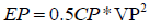
Cp is the capacitance of primary capacitor and Vp is the primary voltage. The primary capacitor is 3nF and it is charged to 12kV then the stored energy can be calculated from equation above.

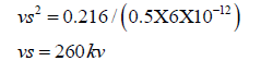
Assuming there are no losses in the transfer of energy to the secondary winding, the conservation of energy states that this energy will be transferred to the secondary capacitance Cs. Cs is typically calculated around 6pF. If it contains 0.216 Joules of energy when the energy transfer is complete, we can calculate the voltage of secondary circuit: Es=0.5 × 6 × 10-12 × Vs2=0.126
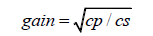
The theoretical voltage gain of the Tesla Coil is actually equal to the square root of the capacitance ratio.
The voltage gain can also be calculated in terms of the inductance for the Tesla Coil to work, the resonant Frequencies of the Primary circuit and the secondary circuit must be identical. i.e. Fp must equal Fs.
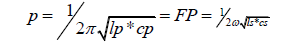
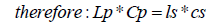
Where, Ls is the inductance of secondary coil equal to 21 millihenery approximately and Cs is the self-capacitance of secondary coil equal to 6 picofarad approximately and Lp is the inductance of primary circuit equal to 44 microhenery. The voltage gain can be calculated from the ratio of the inductances as follows:
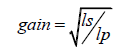
The calculated gain was approximately 22.
Conclusion
The working operation and design analysis of homemade tesla coil is presented in this paper. From fast Fourier transformer, the primary resonance frequency approximately has the same as the secondary resonance frequency, 1 MHz. The calculated voltage gain was approximately 22. This work give us ideas about behavior of corona discharge and high voltage of high frequency that can be used for generation X-ray and generation cold plasma from floating dielectric barrier discharge (FDBD) in the future research.
References
- Craggs JD, Meek JM. High Voltage Laboratory Technique. Butterworths Scientific Publications. 1954.
- Hoffmann CRJ. A Tesla transformer high-voltage generator. In Rev Sci Instrum.1975;46:1-4.
- Sarjeant WJ, Dollinger RE. High Power Electronics. TAB Professional and Reference Books. 1989.
- Denicolai M. Optimal performance for Tesla transformers. Review of Scientific Instruments. 2002;73:3332-36.
- Sloan DH. A Radio frequency high-voltage generator. In Phys Rev. 1935;47.
- Scott MC, O Loughlin JP, Copeland RP. A 350 kV dual resonant transformer for charging a 40 pF PFL at kilo-hertz rep-rates. In: Pulsed Power Conference, 1995. Digest of Technical Papers. Tenth IEEE International. 1995;2:1466-71.
- Scott SA, Skeldon KD, Grant AI. A high potential Tesla coil impulse generator for lecture demonstrations and science exhibitions. In American Journal of Physics. 1997;65.
- Skeldon KD. Development of a portable Tesla coil apparatus. In European Journal of Physics. 2000;21.
- Cvetic J. Tesla's Magnifying Transmitter Principles of Working. First International Congress Nikola Tesla-History ofthe Future 24-26 April 2015. Belgrade. Serbia.
- Tilbury. Mitch. The Ultimate Tesla Coil Design and Construction Guide. New York Mc Graw-Hill Professional, 2007.