Review
, Volume: 13( 1) DOI: 10.37532/2320-6756.2025.13(1).403A Novel CPW-Fed Multiband Planar Monopole Antenna for GSM/WLAN/WiMAX Applications
- *Correspondence:
- Kim Un Chol Department of Physical Engineering, Kim Chaek University of Technology, Kyogu Dong, DPR Korea E-mail: KUC727@star-co.net.kp
Received: September 06, 2023, Manuscript No. TSPA-23-112798; Editor assigned: September 11, 2023, PreQC No. TSPA-23-112798 (PQ); Reviewed: September 26, 2023, QC No. TSPA-23-112798; Revised: January 09, 2025, Manuscript No. TSPA-23-112798 (R); Published: January 16, 2025, DOI. 10.37532/2320-6756.2025.13(1).403.
Citation: Chol KU, Song PY, Gon JH, et al. A Novel CPW-Fed Multiband Planar Monopole Antenna for GSM/WLAN/WiMAX Applications. J Phys Astron. 2025;13(1).404.
Abstract
A novel CPW-fed multiband planar monopole antenna is designed and investigated in this paper. The proposed antenna is fabricated on FR4 substrate and has a compact size of 26 × 45 × 1.6 mm3. A prototype is fabricated and then measured. The simulated and measured results exhibit that the operating bandwidth with a reflection coefficient of less than −10 dB is about 150 MHz (1700–1850 MHz), 310 MHz (2.38–2.69 GHz), 520 MHz (3.23–3.75 GHz), and 820 MHz (5.09–5.91 GHz). These frequency ranges meet the bandwidth requirement for GSM 1800MHz, WLAN 2.4/5.2/5.8 GHz and WiMAX 2.5/3.5/5.5 GHz bands. Also, almost omnidirectional radiation patterns and peak gains of 2.1 dBi at 1.8 GHz, 2.21 dBi at 2.4 GHz, 2.8 dBi at 3.5 GHz, and 4.98 dBi at 5.5 GHz are obtained. The proposed antenna with small size, planar structure, good impedance bandwidth and omnidirectional radiation patterns is very suitable for GSM/ WLAN/WiMAX applications.
Keywords
GSM/WLAN/WiMAX; Multiband antenna; Omnidirectional radiation pattern; Coplanar waveguide
Introduction
Recently, fast growth in wireless communications has increased the demands for mobile terminals offering multiple features. Global System for Mobile Communication (GSM), Worldwide Interoperability for Microwave Access (WiMAX), and Wireless Local Area Network (WLAN) are very popular wireless communication systems and have been widely applied in mobile devices [1–3]. In order to meet GSM (1770-1840 MHz), WLAN (2.4–2.48, 5.15–5.35, and 5.72–5.85 GHz) and WiMAX (2.5–2.69, 3.40–3.69, and 5.25–5.85 GHz) standards simultaneously, multiband antennas with good performance are required. The performance of the antenna which includes the reflection coefficient, radiation pattern, gain and efficiency are considered enough to meet the requirement of the multiband communication systems. Many antennas have been introduced to achieve multiband characteristics. A CPW-fed monopole antenna with double rectangular rings and vertical slots in the ground plane is presented for WLAN/WiMAX applications [4]. Also, a CPW-fed triple-band antenna with metamaterial resonators is presented for wireless communications [5]. A miniaturized triple band monopole antenna with a toothbrush-shaped patch, a meander line and an inverted U-shaped patch is reported for WLAN/WiMAX operations [6]. Triple-band antenna with defected ground structure is proposed for WLAN/WiMAX applications [7]. The antenna with two branches of curved strips is proposed for vehicle communication applications with four resonant frequency bands. Multi-bands circular ring monopole antenna with double Lshape for WLAN/WiMAX applications is presented in Mkindu et al [9]. Multiband monopole antenna with meander line has been presented for wireless communications [10]. Wide CPW-fed multiband wearable monopole antenna with extended grounds is presented for GSM/WLAN/WiMAX applications [11]. However, some of these reported multiband antennas are not sufficient to cover the entire frequency band for GSM/WLAN/WiMAX operations. Meanwhile, some of them are large in size and have complex structures. In this paper, a novel CPW-fed monopole antenna with quadruple band characteristic is proposed for wireless communication application. The proposed antenna operates at 1.8/2.4/3.5/5.2/5.5/5.8 GHz bands. The performances of the proposed quadruple band antenna are investigated by using the CST Microwave Studio software. Simulated and measured results show that the proposed antenna has quad-band characteristics and good omnidirectional radiation patterns which make it suitable for GSM/WLAN/WiMAX communication applications. The paper is organized in the following sections. Antenna design is presented in section 2. In section 3, the simulated and measured results are discussed. Subsequently, section 4 concludes the paper.
Literature Review
Antenna design
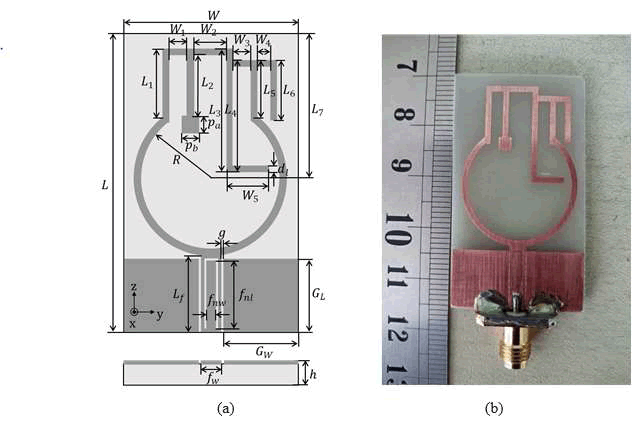
The geometric configuration of the proposed antenna and photograph of the fabricated prototype are shown in Figure 1a and b, respectively. The proposed antenna is printed on an FR4 substrate with relative permittivity of εr=4.4 loss tangent of tan δ=0.02, a thickness of h=1.6 mm and dimensions of 26 × 45 mm2.The antenna is fed by a CPW line which is designed for 50 Ω characteristic impedance. A signal strip width of a 50 Ω CPW transmission line is 3 mm and a gap distance is 0.3 mm. Two ground planes of the CPW line with dimensions of 11.2 × 11 mm2 are situated symmetrically on either side of the CPW line. A SMA connector is connected to the 50 Ω CPW line to feed the antenna.
FIG. 1. Geometry of the proposed antenna (a) Structure, (b) Photograph.
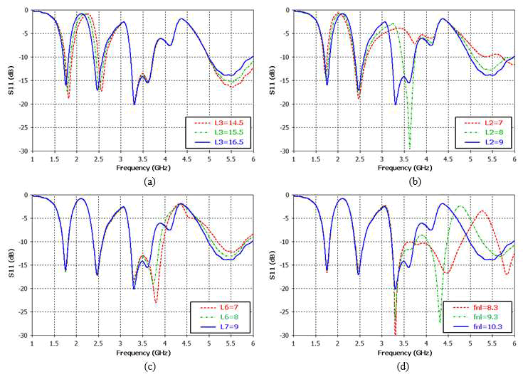
The antenna consists of a circular-shaped strip, a ?-shaped strip connected with an inverted L- shaped strip, an inverted Tshaped strip and a L-shaped strip within ?-shaped strip, and a ?-shaped slot etched on the CPW feed line. The antenna consists of a single-layer metallic configuration for the simple fabrication, which is etched onto one side of the substrate. In order to sufficiently understand the proposed multiband antenna, the key parameters L2, L3, L6, and fnl are selected to investigate their effects on the impedance bandwidth. Figure 2a shows the effects of L3 on the reflection coefficient of the proposed multiband antenna. It is observed from the figure that the center frequencies of the first band near 1800 MHz and the second band near 2.4 GHz move to lower frequency side with an increase of L3 ranging from 14.5 mm to 16.5 mm. In this case, the other resonance frequencies are slightly changed. Figure 2b shows the effect of the parameter L3. As shown in Figure 2b, it is observed that, the parameter L2 has an important effect on the bands near 3.5 GHz and 5.5 GHz. When parameter L3 increases from 7 mm to 9 mm, the resonance frequencies of the third band near 3.5 GHz and fourth band near 5.5 GHz move to lower frequency side. In this case, the other resonance frequencies are almost invariable. Figure 2c shows the effects of on the reflection coefficient of the proposed antenna. As shown in Figure 2c, it is observed that, the parameter L2 has an important effect on the fourth band near 5.5 GHz. As increases from 7 mm to 9 mm, the center frequency of fourth band near 5.5 GHz moves to lower frequency side. At the same time, the other frequency bands are slightly changed. Figure 2d shows the effects of on the impedance bandwidth of the proposed antenna. A ?-shaped slot etched on the CPW feed line is used to reject an unwanted resonance at around 4.5 GHz. When the parameter increases from 8.3 mm to 10.3 mm, the resonance frequencies of the notched band near 4.5 GHz move to lower frequency side. From the discussion above, center resonance frequencies can be adjusted by changing the dimensions of a L-shaped strip, an inverted T-shaped strip, an inverted L-shaped strip, and a ?-shaped slot to make them suitable for GSM/WLAN/WiMAX communication applications. The proposed multiband antenna has been investigated and optimized by the CST Microwave Studio software. The optimized parameters of the antenna are listed as follows: W1=2.5, W2=4.9, W3=2.6, W4=2, W5=6.5, L1=9.98, L2=9, L3=18.5, L4=16.7, L5=7.18, L6=9, L7=21.5, GW=11.2, GL=11, fw=3, fnw=1.4, fnl=10.3, Lf=12.1, dl=1, R=11.5, h=1.6, L=45, W=26, g=0.3. Here all dimensions are in mm.
FIG. 2. The Simulated Reflection Coefficients of the Proposed Antenna with Different Values of L3, L2, L6, and fnl (a) L3, (b) L2, (c) L2, (d) fnl
Results and Discussion
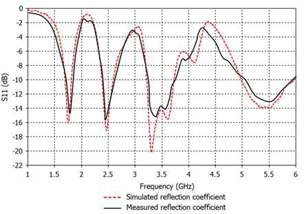
Figure 3 shows the simulated and measured reflection coefficients of the proposed multiband antenna with the optimized parameters, and good agreement between simulation and measurement is observed. The measurement of the fabricated multiband antenna is performed with Agilent Field Fox N9918A vector network analyzer. As shown in Figure 3, the proposed antenna has four different resonance frequencies at 1800 MHz, 2.4 GHz, 3.5 GHz, and 5.5 GHz, which can cover 1800 MHz GSM, 2.4/5.2/5.8 GHz WLAN and 2.5/3.5/5.5 GHz WiMAX operational bands with reflection coefficient of less than -10 dB. The measured bandwidths of the proposed antenna at the desired four different operating bands are 150 MHz (1700–1850 MHz), 310 MHz (2.38–2.69 GHz), 520 MHz (3.23–3.75 GHz), and 820 MHz (5.09–5.91 GHz), respectively.
FIG. 3. The simulated and measured reflection coefficient of the proposed antenna.
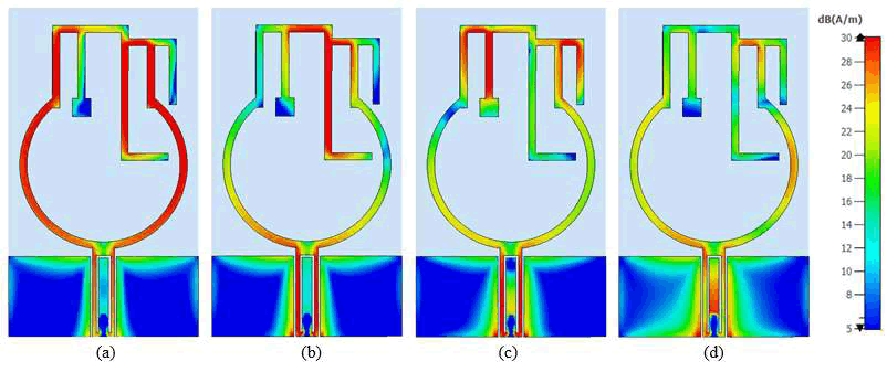
The simulated current distributions of the proposed antenna at the four different resonance frequencies are shown in Figure 4. The larger current distribution is indicated in red, and the smaller one is indicated in blue. As shown in Figure 4, current distributions of the four different resonance frequencies are different from each other. As can be seen from the Figure 4a, current distribution at first frequency band (1800 MHz) mainly focuses on the circular-shaped strip and L-shaped strip within ?-shaped strip. Similarly, as can be seen from the Figure 4b, current distribution at second frequency band (2.4 GHz) mainly concentrates on the L-shaped strip within ?-shaped strip. As can be seen from the Figure 4c and Figure 4d, the current distributions at third frequency band (3.5 GHz) and fourth frequency band (5.5 GHz) mainly appear on the inverted T-shaped strip within a ?-shaped strip and an inverted L- shaped strip.
FIG. 4. The simulated current distribution of the proposed antenna (a) 1.8 GHz, (b) 2.4 GHz, (c) 3.5 GHz, (d) 5.5 GHz
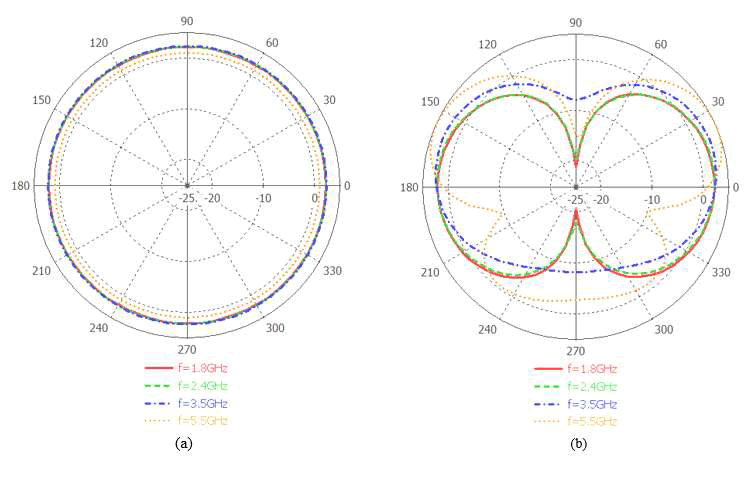
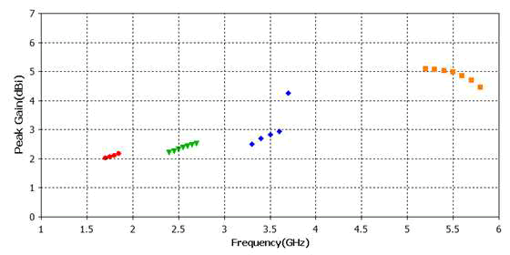
The radiation patterns of the proposed multiband antenna are shown in Figure 5. It can be seen from Figures 5a and 5b that the proposed antenna has good omnidirectional radiation patterns in H-plane (X-Y plane) and bidirectional patterns in E-plane (X-Z plane). The peak gain of the proposed multiband antenna is shown in Figure 6. It is found that the peak gain of the antenna at 1800 MHz, 2.4 GHz, 3.5 GHz and 5.5 GHz are about 2.1 dBi, 2.21 dBi, 2.8 dBi and 4.98 dBi, respectively.
FIG. 5. Radiation Patterns of the Proposed Antenna (a) H-Plane (X-Y Plane), (b) E-Plane (X-Z Plane)
FIG. 6. Peak gain of the proposed antenna.
Comparisons between the proposed antenna and some existing multiband antennas are shown in Table 1. From the Table 1, the proposed antenna with an excellent multiband performance has a smaller size than previously proposed quadruple antennas in Mandal et al. [11,12]. Although previously reported antennas in Yu; Suneel and Kahina et al. have smaller sizes than our designed antenna, they cannot cover all the above mentioned operating bands [13-15].
| Sizes (mm2) | Operating bands |
|---|---|
| 45.5 × 85 | 1.8/2.4/3.6/5.5 |
| 70 × 70 | 1.78/2.4/3.46/5.26 |
| 28 × 41 | 2.4/3.5/5.8 |
| 35 × 25 | 2.4/3.5/5.8 |
| 14.6 × 17.5 | 2.4/3.5/5.8 |
| 26 × 45 | 1.8/2.4/3.5/5.2/.5.5/5.8 |
TABLE 1. Comparisons of several existing. multiband antennas.
Conclusion
In this paper, a novel CPW-fed multiband planar monopole antenna with quadruple band characteristic has been presented. The proposed antenna is fabricated on a low-cost FR4 substrate with dimensions of 26 mm × 45 mm × 1.6 mm. The proposed antenna with planar structure and small size is designed to cover the 1800 MHz GSM, 2.4/5.2/5.8 GHz WLAN, and 2.5/3.5/5.5 GHz WiMAX bands. The measured -10 dB impedance bandwidths are about 150 MHz (1700-1850 MHz)/ 310 MHz (2.38–2.69 GHz)/ 520 MHz (3.23–3.75 GHz)/820 MHz (5.09–5.91 GHz). The peak gains are 2.1 dBi at 1800 MHz, 2.21 dBi at 2.4 GHz, 2.8 dBi at 3.5 GHz, and 4.98 dBi at 5.5 GHz. Also, the good omnidirectional radiation patterns in H-plane are obtained. The proposed multiband monopole antenna with a compact size, planar structure, low cost, ease to manufacture, omnidirectional H-plane radiation patterns, and good impedance bandwidths is well suitable for GSM, WLAN and WiMAX communication applications.
References
- Sun XL, Liu L, Cheung SW, et al. Dual-band antenna with compact radiator for 2.4/5.2/5.8 GHz WLAN applications. IEEE Trans Antennas Propag. 2012;60(12):5924-5931.
- Mehdipour A, Sebak AR, Trueman CW, et al. Compact Multiband Planar Antenna for 2.4/3.5/5.2/5.8-GHz Wireless Applications. IEEE Antennas Wirel Propag Lett. 2012;11:144-147.
- Zhai H, Ma Z, Han Y,et al. A compact printed antenna for triple-band WLAN/WiMAX applications. IEEE Antennas Wirel Propag Lett. 2013;12:65-68.
- Sangjin Jo, Hyunjin Choi, Jaehyuk Lim. A CPW-Fed Monopole Antenna with Double Rectangular Rings and Vertical Slots in the Ground Plane for WLAN/WiMAX Applications. Int J Antennas Propag. 2015; 2015(165270): 1-7.
- Si LM, Lv X. CPW-FED multi-band omni-directional planar microstrip antenna using composite metamaterial resonators for wireless communications. Prog Electromagn Res. 2008;83:133-146.
- Li Y, Yu W. A miniaturized triple band monopole antenna for WLAN and WiMAX applications. Int J Antennas Propag. 2015;2015(1):146780.
- Ibrahim A, Fazil NA, Dewan R. Triple-band antenna with defected ground structure (DGS) for WLAN/WiMAX applications. J Phys Conf Ser. 2020;1432:012071.
- Husnu Y, Huseyin C. Design and analysis of multi-band compact microstrip antenna in GSM1900/WLAN/WiMAX/DSRC/X-BAND frequency bands for vehicle applications. Sci Rep. 2023;2687(6167): 407-418.
- Mkindu H, Iddi H. Multi-bands circular ring monopole antenna with double L-shape for WLAN/WiMAX applications. Tanz J Sci. 2021;47(1):228-242.
- Y. Li, W. Li, R. Mittra. A compact ACS-FED dualband meandered monopole antenna for WLAN and WiMAX applications. Microw Opt Technol Lett. 2013;55(10):2370–2373.
- Mandal D, Pattnaik SS. Wide CPW?fed multiband wearable monopole antenna with extended grounds for GSM/WLAN/WiMAX applications. Int J Antennas Propag. 2019;2019(1):4264513.
- Mandal D, Pattnaik SS. Quad-band wearable slot antenna with low SAR values for 1.8 GHz DCS, 2.4 GHz WLAN and 3.6/5.5 GHz WiMAX applications. Prog Electromagn Res B. 2018;81:163-182.
- Yu K, Li Y, Yu W. A compact triple band antenna for bluetooth, WLAN and WiMAX applications. Appl Comput Electromagn Soc J. 2017;32(5):424.
- Suneel E, Rao BP. CPW-fed Compact Antenna for WiMAX/WLAN Applications. Int J Wirel Microw. Technol. 2019;9:11-24.
- Kahina D, Mouloud C, Mokrane D, et al. A compact ACS-fed tri-band microstrip monopole antenna for WLAN/WiMAX applications. Adv Electromagn. 2018;7(5):87-93.
