Research
, Volume: 13( 1) DOI: 10.37532/2320-6756.2025.13(1).404A Miniaturized Quadruple Band Notched UWB Antenna Using U-Shaped Slots and SRRs
- *Correspondence:
- Kim Dae Il
Department of Physical Engineering, Kim Chaek University of Technology, Kyogu Dong, DPR Korea
E-mail: Sh_kim@star-co.net.kp
Received: September 11, 2023, Manuscript No. TSPA-23-113212; Editor assigned: September 14, 2023, PreQC No. TSPA-23-113212 (PQ); Reviewed: September 29, 2023, QC No. TSPA-23-113212; Revised: January 09, 2025, Manuscript No. TSPA-23-113212 (R); Published: January 16, 2025, DOI. 10.37532/2320-6756.2025.13(1).404.
Citation: Dae-Il K, Chol KU, Song KM. A Miniaturized Quadruple Band Notched UWB Antenna Using U-Shaped Slots and SRRs. J Phys Astron. 2025;13(1).404.
Abstract
In this paper, a novel planar Ultra-Wideband (UWB) antenna with quadruple band-notched characteristics is proposed and investigated. The quadruple band-notched characteristics can be achieved by embedding three U-shaped slots on the radi ation patch and two Split Ring Resonators (SRRs) near feed line, respectively. The proposed antenna was successfully simulated and manufactured. It has a tiny size, only 17 mm × 23 mm × 0.508 mm. The proposed antenna exhibits good wideband performances over an UWB frequency range from 3.1 to 10.8 GHz with S11 less than -10 dB and with the exception of 3.27~3.7 GHz, 3.8~4.8 GHz, 5.13-5.65 GHz, 7.9~8.5 GHz frequency bands. Good agreement is obtained between the simulated results and measured results. The miniaturized structure and good characteristics make the suggested antenna a good candidate for UWB applications.
Keywords
Quadruple notched band; Split ring resonators; Miniaturized structure; Omnidirectional pattern; UWB antenna
Introduction
UWB communication system operates in the frequency band of 3.1 up to 10.6 GHz which has been approved by the U.S. Federal Communication Commission (FCC) in 2002 [1]. Antenna is an indispensable component of wireless device. The optimal performance of the radio communication system depends on the efficient design of antenna in great measure. Therefore, many studies on efficient design of UWB antennas which provide good wideband characteristics have been performed. However, before the approval of UWB, some narrow band communication systems, such as the World Interoperability for Microwave Access (WiMAX) system operating in the 3.5 GHz (3.3~3.7 GHz), C-band satellite communication system operating at the band of 3.8–4.2 GHz, Wireless Local Area Network (WLAN) operating in the 5.25 GHz (5.15–5.35 GHz) and 5.75 GHz (5.725–5.825 GHz), and International Telecommunications Union (ITU) operating at the band of 8.01–8.5 GHz have already existed [2,3]. Therefore, frequency band for UWB communication systems will cause interference to existing narrow band systems. One solution to this problem is to insert band-stop filter to the RF front-end. But this method would increase complexity, cost and size of system. The other better method is to design UWB antennas which incorporate integrated band-notched characteristics. Various techniques have been applied to achieve band-notched properties. One common method focuses on etching various kinds of slots, such as C-shape [4-7], T-shape [8-10], H-shape [11-13], U-shape [14-18], E-shape [19,20], arc-shaped slots, and SRRshaped slot. Another effective method is adding diverse parasitic elements, such as T-shaped and SRR shaped elements. In this paper, a novel compact UWB planar monopole antenna of 17 mm × 23 mm=391 mm2 is presented and fabricated. The initial design of the proposed UWB antenna includes a rectangular patch adding on the circular patch at the top of the dielectric substrate and a defected ground structure at the bottom of the dielectric substrate. The proposed antenna can operate from 3.1 to 10.8 GHz to cover entire UWB range with VSWR less than 2. By etching three U-shaped slots on the radiation patch and adding two SRRs near the feed line, the proposed antenna can produce quadruple notched bands at 3.27~3.7 GHz, 3.8~4.8 GHz, 5.13~5.65 GHz, 7.9~8.5 GHz to give resistance to the interferences from narrow band communication systems. The proposed antenna was manufactured and measured with optimal dimensions. This paper is organized in the following 4 sections. Geometrical structure and design procedure of the proposed antenna are shown in section 2. In section 3, parametric study is presented. In addition, current distribution, radiation pattern and realized gain are shown. Finally, section 4 presents the conclusion.
Materials and Methods
Antenna Design
Schematic and dimensions of the proposed antenna: The proposed quadruple band-notched antenna is based on a planar monopole UWB antenna. Figure 1 depicts the configuration and the fabricated prototype of the proposed antenna. As you can see from Figure 1, the proposed antenna consists of aradiator with three U-shaped slots, feedline and two SRRs near the feed line on the front surface of the substrate. On the back surface of the substrate, there is a defected ground structure with inverted U-shaped slot. The proposed antenna is printed on a Rogers 4350 B substrate with relative permittivity of 3.66, loss tangent of 0.0037 and thickness of 0.508 mm. The total size of the antenna is 17 mm × 23 mm=391 mm
FIG. 1. Geometrical structure and photograph of the proposed antenna (a) Geometrical structure, (b) Photograph.
| Parameters | Ws | Ls | Ws1 | Ls1 | G | Wf | Pf | R | R1 | R2 | R3 |
|---|---|---|---|---|---|---|---|---|---|---|---|
| Values(mm) | 17 | 23 | 14.5 | 4.1 | 0.9 | 1.1 | 2.4 | 8 | 6.6 | 5.75 | 3.7 |
| Parameters | R4 | P4 | Lg | Lslot | Up | UL | Uw | Wu | WR | WD | |
| Values(mm) | 2.05 | 4.15 | 6 | 4.3 | 5.3 | 0.5 | 2.4 | 0.25 | 0.25 | 0.3 |
TABLE 1. Optimized parameters of the proposed antenna.
Design procedure of the proposed antenna: The design procedure of the proposed antenna is described in Figure 2. We will show how to design the proposed quadruple band-notched antenna step by step. Firstly, we used a UWB antenna which is denoted Ant1 for designing the proposed antenna. Ant 1 covers UWB band 3.1-10.6 GHz. The upper frequency of impedance bandwidth is affected by an inverted U-shaped slot in the ground plane. Therefore, by adjusting the length of an inverted Ushaped slot, we can control impedance bandwidth. Then the first U-shaped slot is etched on the radiation patch to create Ant 2 which is to design the first rejected band at 3.5 GHzWiMAX band. And also the second U-shaped slot is etched on the radiation patch to construct Ant 3 which is to design the second notched band at C-band satellite communication band. Then, third Ushaped slot is etched on the radiation patch to create Ant 4 which is to design the third notched band at 5.25 GHzWLAN band. Last, we add two SRRs near the feed line to construct Ant 5 which is to provide the forth notched band at ITU band.
FIG. 2. Design procedure of the proposed antenna.
Results
Parameter analysis
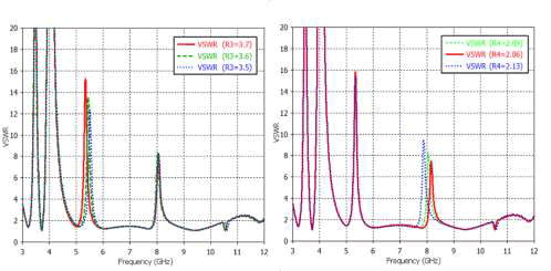
We will investigate parameter effects on the VSWR. Here, the parameters R1,R2,R3 and Rt are selected for evaluating the effects on the proposed quadruple band-notched UWB antenna. Figure 3a shows that R1 has important effects on the 3.47 GHz frequency center band. By adjusting the value of R1 from 6.4 mm to 6.8 mm, center of the first notched band shifts slightly for lower frequencies side: from 3.54 GHz to 3.38 GHz. On the other hand, we can observe that the parameter R1 has small influences for three other notched bands 4.1 GHz, 5.33 GHz and 8.1 GHz. Figure 3b shows that R2 makes a great impact on the 4.1 GHz frequency center band. By adjusting the value of R2 from 5.6 mm to 5.9 mm, center of the second notched band shifts slightly for lower frequencies side: from 4.17 GHz to 4.04 GHz. Also, it is found that the parameter R2 has a little influence for three other notched bands 3.47 GHz, 5.33 GHz and 8.1 GHz. Figure 4a shows that R3 affects greatly on the 5.33 GHz frequency center band. By adjusting the value of R3 from 3.5 mm to 3.7 mm, center of the third notched band shifts slightly for lower frequencies side: from 5.51 GHz to 5.33 GHz. On the other hand, we can observe that the parameter R3 has small influences for three other notched bands 3.47 GHz, 4.1 GHz and 5.33 GHz. Figure 4b shows that R4 has a great influence on the 8.1 GHz frequency center band. By adjusting the value of R4 from 2.06 mm to 2.13 mm, center of the forth notched band shifts slightly for lower frequencies side: from 8.21 GHz to 7.86 GHz. On the other hand, we can observe that the parameter R4 has a little influence for three other notched bands 3.47 GHz, 4.1 GHz and 5.33 GHz.
FIG. 3. The Simulated VSWR of the Proposed Antenna with Changes of R1 and R2 (a)R1, (b)R2.
FIG. 4. The Simulated VSWR of the proposed antenna with changes of R3 and R4 (a) R3, (b) R4.
To confirm the effectiveness of the proposed antenna, the optimized antenna is manufactured and its VSWR is measured by using Agilent Field Fox N 9918A vector network analyzer. Figure 5 shows comparison between the measured and simulated VSWR results of the proposed antenna. As you can see from Figure 5, the measured notched frequencies and impedance bandwidth of the proposed antenna are very suitable for suppressing the intrusion from WiMAX system, WLAN, C-band satellite communication system and ITU. The measured frequency range covers commercial UWB band (3.1–10.6 GHz) and has four notched frequency bands of 3.27–3.7 GHz (12.34%), 3.8-4.8 GHz (23.3%), 5.13–5.65 GHz (9.65%), and 7.9-8.5 GHz (7.3%). There is a little discrepancy between the measured and simulated results, which may be caused by fabrication tolerance and interference of connector and feeding cable in the measurement.
FIG. 5. Simulated and measured VSWR of the proposed antenna.
Current distribution
The current distribution of the proposed antenna is investigated and explained in Figure 6. As you can see in Figure 6a, current density is highly concentrated at three U-shaped slots at 3.47 GHz, 4.1 GHz, 5.33 GHz respectively and at two SRR sat 8.1 GHz. This means that a large part of electromagnetic energy has been stored around three U-shaped slots or two SRRs on the front surface of the substrate. So radiation efficiency decreases at the rejected bands. As can be seen in Figure 6b, surface current at the pass band of 3.75 GHz, 5 GHz, 6.7 GHz and 9 GHz is hardly concentrated close to three U-shaped slots and SRRs while it is highly concentrated around the edge of the main radiator. Thus, signal is propagated.
FIG. 6. The Current Distribution of the Proposed Antenna (a) stopband, (b) passband. The Current Distribution of the Proposed Antenna (a) stopband, (b) passband.
Radiation patterns and realized gain
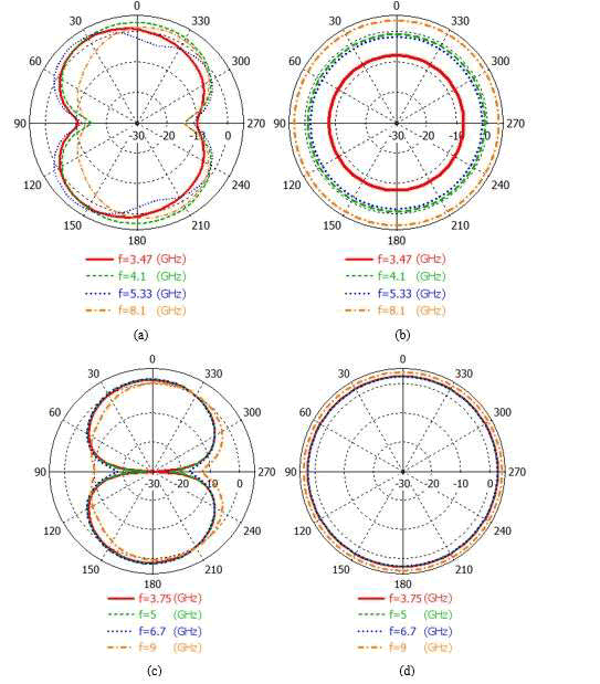
Figure 7 illustrates radiation patterns in E-plane (X-Z plane) and H-plane (X-Y plane) at stop bands of 3.47 GHz, 4.1 GHz, 5.33 GHz and 8.1 GHz and at pass bands of 3.75 GHz, 5 GHz, 6.7 GHz and 9 GHz. From Figure 7, we can observe that radiation pattern in E-plane looks like a digit ‘8’and is faintly distorted as frequency becomes higher. H-plane radiation patterns conserve nearly omnidirectional characteristics at almost every frequency.
Fig. 7. Radiation patterns of the proposed antenna. (a) E-Plane (X-Z Plane) at the Stopband Frequencies (b) H-Plane (XY Plane) at the stopband frequencies (c) E-Plane (X-Z Plane) at the passband frequencies (d) H-Plane (X-Y Plane) at the passband frequencies.
Realized gains of the proposed antenna with and without notched band structures are shown in Figure 8. As you can see, antenna gain drops very quickly in the vicinity of four notched band frequencies of 3.47 GHz,4.1 GHz,5.33 GHz and 8.1 GHz. It means that radiation ability of the proposed antenna is strong at UWB band except quadruple notched bands. This clearly illustrates quad band rejection function of the proposed antenna. Table 2 gives comparisons of the proposed antenna with previously introduced band-notched UWB antennas. As you can see from Table 2, many triple or quadruple band-notched UWB antennas have been introduced so far. In NedaRojhani, a miniaturized design of UWB antenna have been introduced but it has achieved only triple notched bands. And also in Chaabane Abdelhalim, not only they provide triple notched bands but also they are fabricated in larger size than this work. In Xiaoyin Li, they provide quadruple notched bands but size of them are bigger than this work. In a word, the proposed UWB antenna provides four notched band, compact size and good band notched properties, making it possible to satisfy the requirements of UWB systems.
FIG. 8. Realized gain of the proposed antenna.
| Number of notches | Notched bands, GHz | Bandwidth, GHz | Size, mm2 |
|---|---|---|---|
| 4 | 5.15-5.35,5.75-5.85, 7.25-7.75, 8.01-8.55 | 3.1-12 | 26 28 |
| 3 | 1.6-2.66, 3-4, 5.13-6.03 | 3.1-10.6 | 31 31 |
| 3 | 2.45-3.0, 3.1-3.7, 3.8-4.3 | 2.0-10.75 | 34.9 31.3 |
| 4 | 3.3-3.6, 5.25-5.35, 5.725-5.825, 7.9-8.4 | 2.94-12 | 20 35.6 |
| 4 | 3.41-4.07, 4.41-4.76, 5.21-5.64, 6.92-8.63 | 2.9-12 | 20 24 |
| 3 | 3.0-3.8, 5.1-6.1, 7.8-8.9 | 2.8-12.5 | 20 14 |
| 4 | 3.6-3.8, 4.5-4.9,5.6-6.0, 7.2-7.6 | 3-10.7 | 20 25 |
| 4 | 3.27~3.7, 3.8-4.8, 5.13-5.65, 7.9~8.5 | 3.1-10.8 | 17 23 |
TABLE 2. Comparisons with proposed band-notched UWB antennas.
Conclusion
This paper presents a study on miniaturized UWB antenna with quadruple band-notched characteristics. Performance of the proposed antenna has been investigated in detail. The quadruple band notched antenna with three U-shaped slots on the radiation patch and two SRRs near the feed line are designed and implemented for suppressing intrusion from WiMAX, C-band satellite communication system, WLAN and ITU band. By simply changing dimensions of corresponding notched band structure, notched-frequency bands can be controlled independently. The proposed antenna shows band rejection at the intended notch frequencies and surface current validates this result. Results show that the antenna has compact size, simple structure and good omnidirectional radiation patterns, making it suitable for UWB communication system.
References
- Azim R, Islam MT, Misran N. Compact tapered-shapeslot antenna for UWB applications. IEEE Antennas and Wireless Propagation Letters. 2011;10:1190–1193.
- Yadav A, Sethi D, Khanna RK. Slot loaded UWB antenna: Dual band notched characteristics. AEU Int J Electron Commun. 2016;3(70):331-335.
- Xu J, Shen DY, Wang GT, et al. A Small UWB Antenna with Dual Band-Notched Characteristics. Int J Antennas Propag. 2012; 626858:1-7.
- Li X, Yan L, Pan W, et al. A Compact Printed Quadruple Band?Notched UWB Antenna. Int J Antennas Propag. 2013;2013(1):956898.
- Abdelhalim C, Farid D. A Compact Planar UWB Antenna with Triple Controllable Band?Notched Characteristics. Int J Antennas Propag. 2014;2014(1):848062.
- Dong D, Chen S, Liao Z, et al. A CPW?Fed Dual?Band?Notched Antenna with Sharp Skirt Selectivity for UWB Applications. Int J Antennas Propag. 2014;2014(1):629387.
- Mohammadi B, Valizade A, Nourinia J, et al. Design of a compact dual?band?notch ultra?wideband bandpass filter based on wave cancellation method. IET Microw Antennas Propag. 2015 9(1):1-9.
- Ojaroudi N, Ojaroudi M, Ghadimi N. Dual band?notched small monopole antenna with novel W?shaped conductor backed?plane and novel T?shaped slot for UWB applications. IET Microw Antennas Propag. 2013;7(1):8-14.
- Ur?Rehman M, Abbasi QH, Akram M, et al. Design of band?notched ultra wideband antenna for indoor and wearable wireless communications. IET Microw. Antennas Propag. 2015;9(3):243-251.
- Sung, Y. Triple band-notched UWB planar monopole antenna using a modified H-shaped resonator. IEEE Trans Antennas Propag. 2013;61(2): 953–957.
- Shi R, Xu X, Dong J, et al. Design and analysis of a novel dual band?notched UWB antenna. Int J Antennas Propag. 2014;2014(1):531959.
- Sarkar D, Khan T, Talukdar FA. Multi?adaptive neuro?fuzzy inference system modelling for prediction of band?notched behaviour of slotted?UWB antennas optimised using evolutionary algorithms. IET Microw Antennas Propag. 2020;14(12):1396-1403.
- Rai VK, Kumar M. Tunable inverted u-shaped dual band notch monopole antenna for ultra wide band applications. IETE Journal of Research. 2023 Sep 7;69(7):4451-60.
- Tak V, Pareek DK. Butterfly shaped single band notch monopole antenna for UWB application. Int J Electr Eng Technol. 2020;11(1):15-25.
- Manohar M, Kshetrimayum RS, Gogoi AK. A Compact Dual Band-notched Circular Ring Printed Monopole Antenna for Super-wide band Applications. Radio engine. 2017; 26(1):64-70.
- Babu PR, Ramakrishna D, Ensermu G. Triple Band?Notch UWB Antenna Embedded with Slot and EBG Structures. Wireless Communications and Mobile Computing. 2023;34611751:1-12.
- Mehranpour M, Nourinia J, Ghobadi C, et al. Dual band-notched square monopole antenna for ultrawideband applications. IEEE Antennas Wirel Propag Lett. 2012;11:172–175.
- Zhu XF, Su DL. Symmetric E?shaped slot for UWB antenna with band?notched characteristic. Microw Opt Technol. 2010;52(7):1594–1597.
- Kong Y, Li Y, Yu W, et al. A quadruple band-notched UWB antenna by using arc-shaped slot and rotated E-shaped resonator. Appl Comput Electromagn Soc J. 2016:1315-21. 2016;31(11):1315-1321.
- Yan B, Jiang D, Xu R, et al. A UWB Band?Pass Antenna with Triple?Notched Band Using Common Direction Rectangular Complementary Split?Ring Resonators. Int J Antennas Propag. 2013;2013(1):934802.


