Original Article
, Volume: 5( 2)Integrating Both a Conventional Integrator and a Fuzzy-Neural-Based PD-Type Controller for an Astronomical Antenna Tracking System Design with Parameter Variations and Servo Hysteresis Effects
- *Correspondence:
- Jium-Ming Lin, Department of Electronic Engineering, Chung-Hua University, Hsin-Chu, 30012, Taiwan, Tel: +886-3-5186483; E-mail: jmlin@chu.edu.tw
Received: May 3, 2017; Accepted: May 15, 2017; Published: May 26, 2017
Citation: Lin JM, Lin CH. Integrating Both a Conventional Integrator and a Fuzzy-Neural-Based PD-Type Controller for an Astronomical Antenna Tracking System Design with Parameter Variations and Servo Hysteresis Effects. J Phys Astron. 2017;5(2):113.
Abstract
Firstly, the tracking and the stabilization loops for an astronomical antenna tracking system were designed according to the requirements such as bandwidth and phase margin. However, the performances would be degraded if either the tacking loop gain was reduced or the hysteresis effect of servo was enlarged. Thus the PID-based fuzzy-neural controlled was applied the next. But the computing time was very large with 343 rules. This paper proposed two methods to solve this problem. Firstly, a new optimization method was proposed by applying various neural network training algorithms, e.g. gradient descent (GD), scaled conjugate gradient (SCG), and Levenberg-Marquardt (LM) optimization methods are applied alternatively in each step of iteration to determine the optimal parameters of the neural controller. Secondly, a hybrid controller was applied by integrating both a conventional integrator and a fuzzy-neural-based PD-type controller, so that not only the computing time could be reduced, but the error at steady state can be equal zero. Note that the system performances obtained by the proposed method were better not only for parameter variations but hysteresis effects in the system. Thus it was more robust.
Keywords
Antenna tracking system; Fuzzy-neural controller; PID controller; Parameter variations; Hysteresis effects
Introduction
In order to lock on the small signals delivering from the further outer space, the performances of astronomical antenna tracking system should be raised in spite of disturbances [1-3], so it is necessary to improve antenna tracking response, pointing precision and attitude stability. The traditional PI (Proportion and Integration) compensator was applied in the control system of mobile antennas to lock on the satellites [4]. This kind of control system design method can be divided into two steps: Firstly, using PID compensators in the antenna control system to meet the requirements of bandwidth and phase margin. Secondly, analyzing both time and frequency responses to obtain the key parameters of antenna control system. Noted the performances of this method would be better in normal conditions, but if the parameter variation and hysteresis effects exist in the system, then the performances would become worse. Thus the fuzzy controller was applied to solve it by using the intelligent fuzzy-neural-based PID controller [5]. However, the computing time would become very large.
To low the computing time, some neural network training algorithms, namely, gradient descent (GD), scaled conjugate gradient (SCG), and Levenberg-Marquardt (LM) methods were applied alternatively in the iteration steps. Besides, to make the steady state error being zero, this paper proposes a hybrid controller to integrate both a conventional integrator and a fuzzy-neural-based PD-type controller for the control system design. Note that the previous problem can be solved. The content of this paper is as follows: the introduction of an astronomical antenna tracking system is at the first section. The traditional PI-based design is followed. Section 3 briefs the evaluation using the traditional PI-based controller. The proposed methods and the improvement analyses are given in Sections 4 and 5, respectively. The last part is the conclusions.
Traditional astronomical antenna control system design
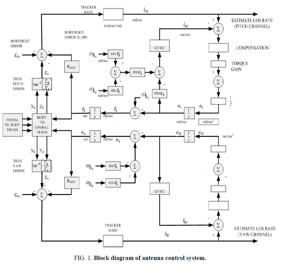
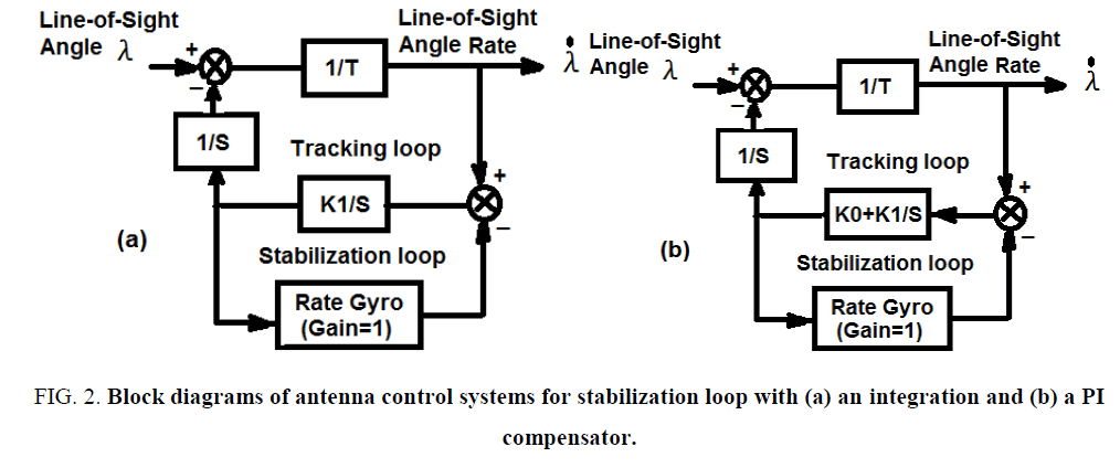
The detailed block diagram of an antenna control system is shown in Figure. 1 [6-10]. It is very difficult to obtain the key parameters for analyses. Thus in general a simplified model of antenna control system as shown in Figure. 2 is applied to speed up the design, in which the tracking loop is modeled as a simple gain, and the stabilization loop is replaced by a pure integration (Figure. 2a), or PI compensators (Figure. 2b). The tracking loop time constant (T) is set as 0.1 seconds in practice. Then the time and frequency domain analyses are taken firstly to obtain the key parameters of the antenna control system.
Figure 2: Block diagrams of antenna control systems for stabilization loop with (a) an integration and (b) a PI compensator.
Controller with pure integrator
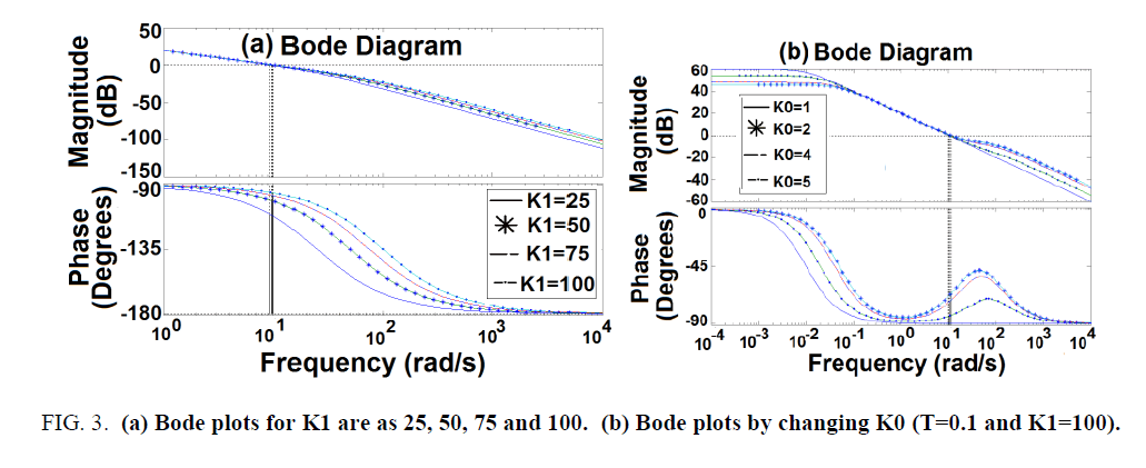
Firstly, a pure integrator is applied in the stabilization loop. By trial-error-method the integrator gain (K1) of stabilization loop is set as 25, 50, 75 and 100, respectively. From Figure. 3 of Bode plots, the phase margins are increased with larger K1 and saturate at 90 degrees for K1=100. So the improvement is limited [11].
Figure 3:(a) Bode plots for K1 are as 25, 50, 75 and 100. (b) Bode plots by changing K0 (T=0.1 and K1=100).
Controller with PI compensator
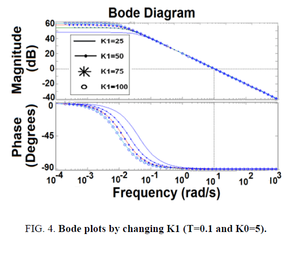
The next was to apply a PI compensator. The gains of P and I compensators are specified as K0 and K1, respectively. If T=0.1 and K1=100, Figure. 3 shows the Bode plots by changing K0, the phase margin is larger for K0=5. Figure. 4 shows the phase margin is insensitive by varying K1 (T=0.1 and K0=5), but the steady-state error is smaller for larger K1. After trial-and-error the phase margins are 132° and 133° for the cases with K0=5, K1=50, T=0.1 and K0=5, K1=25, T=0.2, respectively. Note that the former is faster for T=0.1.
Performance analyses with PI-based controller design
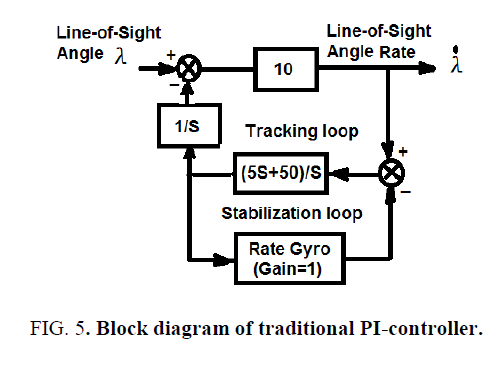
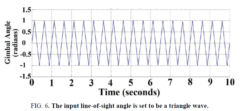
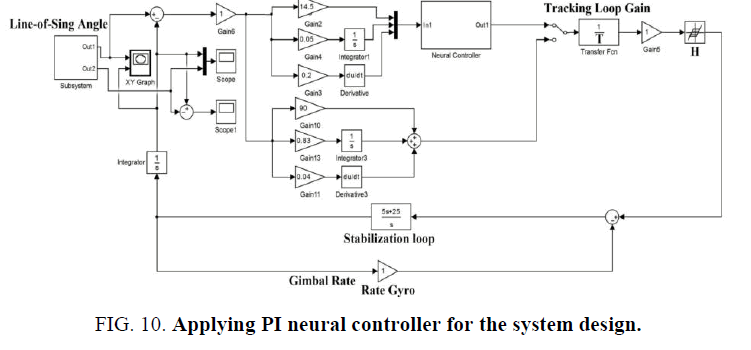
Figure. 5 shows the block diagram of the antenna control system, the simulation method was applied to check the performance. The input line-of-sight angle was set as a triangular wave (amplitude=1 radian and period=5 seconds) as shown in Figure. 6. The error responses between the input and output gimbal angles by using the previous PI-based controller with backlash effect (H=0.1) is shown in Figure. 7, note the antenna tracking error is 0.05 radians, also noted that the performance is very good.
Figure 7: Error response between input and output gimbal angles by using traditional PI-controller with T=0.1 and H=0.1.
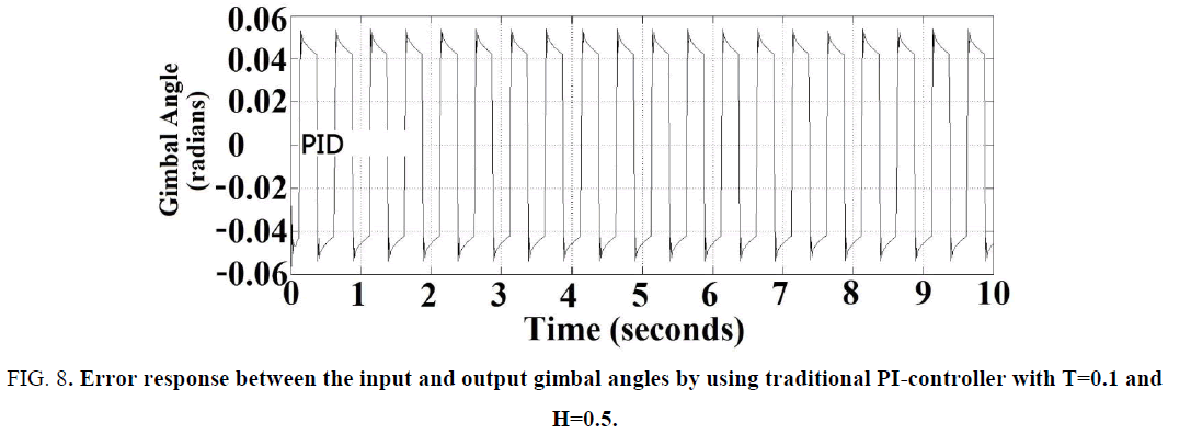
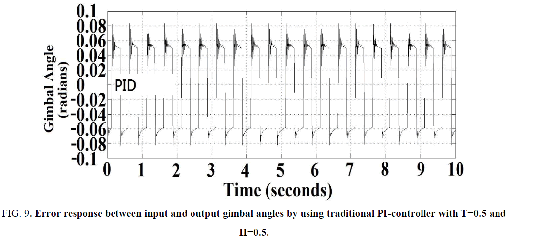
However, if the servo hysteresis effect becomes larger, i.e., H=0.5. The error response between input and output gimbal angles was shown in Figure. 8 . Note that the largest tracking error of gimbal angle was 0.055 radians. Moreover, if the pointing error of the antenna is larger, then the tracking-loop gain T would be generally reduced to 2 (i.e., T=0.5) instead of the original 10 (i.e., T=0.1), the error response between input and output gimbal angles was shown in Figure. 9 . Note the largest antenna tracking error became larger as 0.08 radians in the positive cycles, the system overshoot and stability would become worse, because there were some oscillations in the positive cycles of output response. Thus one should find some methods to solve this problem as proposed in the following sections.
Figure 8: Error response between the input and output gimbal angles by using traditional PI-controller with T=0.1 and H=0.5.
Figure 9: Error response between input and output gimbal angles by using traditional PI-controller with T=0.5 and H=0.5.
New optimization method
Artificial neural networks (ANNs) have been widely applied in various fields to overcome the problem of parameter variations and nonlinear effects. Back-propagation neural network (BPNN) is the most effective method to train the ANN model [10]. Depending on the given numbers of known input vectors and its corresponding output vectors, BPNN can be used to train a network to meet the requirement. During the training period, the procedure of the BPNN repeatedly adjusts the weights of the connections in the network using the gradient descent method, so it can minimize the difference between the actual output vector of the network and the desired output vector. And then BPNN model can yield the desired output vector that is similar to the actual output vector. However, BPNN generally converges slowly and would be trapped in the local minimum easily. To avoid these disadvantages, various training algorithms have been proposed to speed up the training. Conjugate gradient algorithms are the most popular iterative methods for solving very large linear systems of equations [12-15]. The Levenburg-Marquardt (LM) method has the most efficient convergence during the back-propagation training process because it can be thought of as a combination of two methods: steepest-descent method with stable but slow convergence, and Gauss-Newton method with opposite characteristics [16]. To increase the effectiveness of the optimization algorithm and reduce the computation time, this paper applied a new method in reference [17] to use various neural network training algorithms, such as gradient descent (GD), scaled conjugate gradient, and Levenberg-Marquardt optimization methods alternatively in each step of iteration to determine the neural controller.
PID-based neural controller design
To solve the parameter variations and the servo nonlinear hysteresis effects, firstly the PID-based neural controller were applies for the system design as shown in Figure. 10. The structure of the neural controller was with three inputs, one hidden layer and one output as shown in Figure. 11
The parameters of the neural controller (using 343 PID rules) and the error response between input and output gimbal angles with T=0.1 and H=0.1 were listed as in TABLE 1 and shown in Figure. 12, respectively. Note that the performance was very good. Moreover, The error responses between input and output gimbal angles with T=0.1, H=0.5 and T=0.5, H=0.5 were also shown in Figure. 13 and Figure. 14 , respectively. Note the antenna tracking performances and stability of neural controller under the parameter variation and servo hysteresis effect were still good without any degradation effects produced by using the PI controller. But the larger computation time was the cost.
| Input Layer to Hidden Layer Weighting Factors | ||
|---|---|---|
| 1st(W1, j) | 2nd(W2, j) | 3rd(W3,j) |
| -0.91183446184803996 | -0.90355622940791869 | -70.063584680030743 |
| 5.9581297643237347e-16 | 2.0654426525074784e-16 | 2.2652173343473186e-12 |
| -1.9311644631618981e-05 | 9.9787706716650761e-05 | 19.508925356309685 |
| Input Layer to Hidden Layer Bias (B1, B2, B3). | ||
| 3.7519331092422048 | -3.7417988623462288 | -79.225868706475424 |
| Hidden Layer to Output Layer Weighting Factors(W3,j) | ||
| -2369.6108227308468 | -2372.5859762426826 | 0.0069870443542015929 |
| Hidden Layer to Output Layer Bias (B4) | ||
| -2.9113180719768073 | ||
TABLE 1: Weightingfactors and biasesof neural network (343 PID rules) combining GD, LM and SCG algorithms.
Figure 12: Error response between input and output gimbal angles for neural controller (343 PID rules) with T=0.1 and H=0.1.
Figure 13: Error response between input and output gimbal angles for neural controller (343 PID rules) with T=0.1 and H=0.5.
Figure 14: Error response between input and output gimbal angles for neural controller (343 PID rules) with T=0.5 and H=0.5.
Proposed hybrid controller
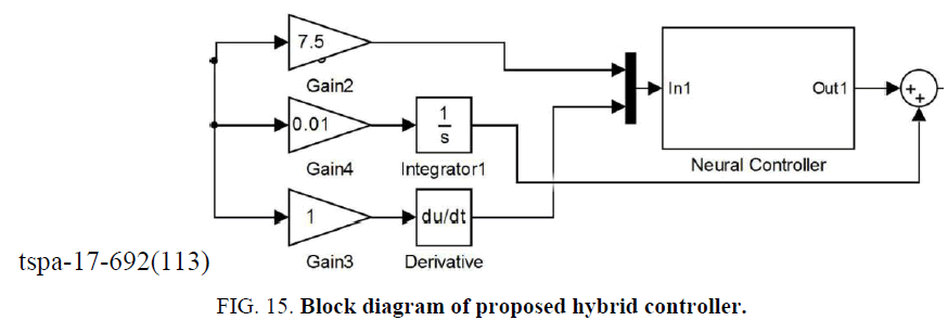
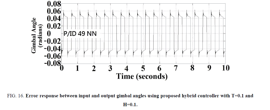
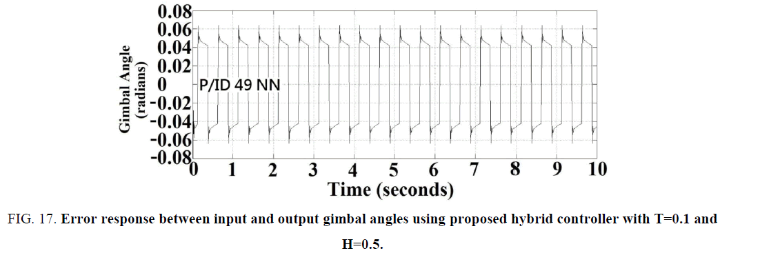
In this section a hybrid controller as shown in Figure. 15 was proposed by integrating both a conventional integrator and a fuzzy-neural-based PD-type controller, so that not only the computing time could be reduced, but the steady state error can be kept as zero. The parameters of the hybrid controller (using 49 PID rules) were listed in TABLE 2. The error responses between input and output gimbal angles for the time constant and hysteresis parameters in the tracking-loop with combinations (T=0.1, H=0.1), (T=0.1, H=0.5), and (T=0.5, H=0.5) are also shown in Figure. 16-Figure. 18, respectively. The Note the antenna tracking performances of the proposed hybrid controller under the parameter variation and hysteresis effect are almost identical to those of the neural controller with 343 PID rules without any degradation effects produced by using the PI controller, but the computation time is reduced as one seventh, because only 49 rules was applied instead of 343 ones.
| Input Layer to Hidden Layer Weighting Factors | ||
|---|---|---|
| 1st(W1, j) | 2nd(W2, j) | 3rd(W3,j) |
| -4.0962239606370847 | -0.89579132561445596 | -4.091888358671202 |
| 8.4457733479342184e-18 | -1.8852006346050587e-18 | -2.4538549107109119e-17 |
| Input Layer to Hidden Layer Bias (B1, B2, B3). | ||
| 3.4098540264824488 | 9.2395096718480202e-05 | -3.4099911932096685 |
| Hidden Layer to Output Layer Weighting Factors(W3,j) | ||
| -4.6856262210421313 | -10.984045855394722 | -4.7079185132110783 |
| Hidden Layer to Output Layer Bias (B4) | ||
| -0.021231599450224469 | ||
TABLE. 2: Weightingfactors and biasesof neural network (49 P/ID rules) combining GD, LM and SCG algorithms.
Figure 16: Error response between input and output gimbal angles using proposed hybrid controller with T=0.1 and H=0.1.
Figure 17: Error response between input and output gimbal angles using proposed hybrid controller with T=0.1 and H=0.5.
Figure 18: Error response between input and output gimbal angles using proposed hybrid controller with T=0.5 and H=0.5.
Conclusion
The antenna control system of an astronomical system was designed using PID method according to the bandwidth and phase margin requirements, firstly. However, the performances would be lowered if either the tacking loop gain was reduced or the servo hysteresis effect became enlarged. To solve these parameter variations and servo hysteresis effects, this paper proposed a PID-based fuzzy-neural controller to solve the problem, but the cost was the computation time for the controller with 343 rules. To reduce the computation time, this paper applied an optimization method by applying GD, SCG, and LM optimization methods alternatively in each step of iteration to determine the PID-based fuzzy-neural controller. Finally, to make the steady state error being zero and reduce the computation time, this paper proposed a hybrid controller by integrating both a conventional integrator and a fuzzy-neural-based PD-type controller for the system design. The results show that not only the performances were better for the normal conditions, but the performance degradation effects in the tracking loop gain reduction and servo hysteresis effects can be reduced. Thus the proposed system was more robust.
Acknowledgments
This research was supported by National Science Council Taiwan, R.O.C. with contracts MOST 105-2622-E-216-005-CC2, MOST 104-2221-E-216-021, and MOST 103-2221-E -216-022.
References
- Densmore AC, Jamnejad V. Two WKa-band mechanically steered and mobile antennas for the NASA ACTS mobile terminal. Proceeding Advanced Communications Technology Satellite Program Conference. NASA, Wash. D.C. 1992.
- Jamnejad V,Densmore AC. A dual frequency WKa-band small reflector antenna for use in mobile experiments with the NASA advanced satellite communications technology. IEEE APSIURSI Joint Intern. Sym. URSI Digest. 1992:1540.
- Densmore AC, Jamnejad V. A satellite-tracking K- and Ka-band mobile vehicle antenna system. IEEE Trans. on Vehicular Technology. 1993;42:502-13.
- Tseng HC,Teo DW. Ship mounted satellite tracking antenna with fuzzy logic control. IEEE Transactions on Aerospace and Electronic Systems. 1998;342:639-45.
- Zhang Y, Hearn GE,Sen PA. A neural network approach to ship track-keeping control. IEEE Journal of Oceanic Engineering. 1996;21:513-27.
- Zhang H, Liu D. Fuzzy Modeling and fuzzy control. New York. Springer-Verlag. 2006.
- Pheysey RL. AIM-9L. Simulation parameters. Naval Weapons Center: China Lake. Calif. NWC.1975.
- Foy W. Position-location solutions by Taylor series estimation. IEEE Transactions on Aerospace and Electronic Systems. AES-12. 1976:187-93.
- Torrieri D. Statistical theory of passive location systems. IEEE Transactions on Aerospace and Electronic Systems. AES-20. 1984:183-97.
- Rumelhart DE, Hinton GE, Williams RJ. Learning representations by back-propagating errors. Nature. 1986;323:533-536.
- Chang PK, Lin JM. Integrating traditional and fuzzy controllers for mobile satellite antenna tracking system design. in Proceedings of WSEAS Conference on Advances in Applied Mathematics, Systems, Communications and Computers selected papers from Circuits, Systems and Signals 2008, June 1-3, 2008. Marathon Beach. Attica. Greece. 2008:102-8.
- Venkatachalan AR,Sohl JE. An intelligent model selection and forecasting system. Journal of Forecasting. 1999; 18:167-80.
- Van Rooyen P,Lotter M,VanWyk D. Space-time processing for CDMA mobile communications. New York. Kluwer.2000.
- Caffery J. A new approach to the geometry of TOA location. Proceedings of IEEE Vehicular Technology Conference. 24-28 September 2000. Boston. MA. USA. 2000:1943-49.
- Møller MF. A scaled conjugate gradient algorithm for fast supervised learning. Neural Networks. 1993;6:525-33.
- Hagan MT,Menhaj MB. Training feedforward networks with the Marquardt algorithm. IEEE Transactions on Neural Networks. 1994;5:989-93.
- Lin JM, Lin CH. Novel intelligent neural guidance law by using multi-optimization algorithms. Journal of Marine Science and Technology, 2016;24:1-14.
