Original Article
, Volume: 8( 2)Comparative Study of the Hybrid Solar Thermal Photovoltaic Collectors Based on Thin Films Solar Cells in South of Algeria
- *Correspondence:
- H Haloui, Renewable Energy Research Unit, URAER, Center for the Development of Renewable Energies, CDER, 47133, Ghardaia, Algeria, Tel: 213023189051; E-mail: haloui_h@uraer.dz
Received: September 13, 2017; Accepted: September 29, 2017; Published: October 11, 2017
Citation: Haloui H, Touafek K, Zaabat M, et al. Comparative Study of the Hybrid Solar Thermal Photovoltaic Collectors Based on Thin Films Solar Cells in South of Algeria. Res Rev Electrochem. 2017;8(2):109
Abstract
The photovoltaic collectors have proved great efficiency in the solar energy power conversion; however, different PV and hybrid thermal collectors are being attracting many researchers. Throughout this attempt, a PVT based on thin-film solar cells based on different technologies (binary, ternary and quaternary materials) has been put in reliability study. In this paper different generations have been discussed. The energy balance equations for different configurations have been described. The analytical expressions for electrical and thermal efficiencies have been calculated through a Matlab simulation (1D) and ANSYS Software (3D). It has been averred that the obtained efficiency by the PVT collectors based on cadmium telluride (CdTe), copper indium diselenide (CIS) and copper indium gallium diselenide (CIGS) is more important than once obtained by PVT collectors based on silicon and amorphous silicon (a-Si), within a rate from 47% to 57%, furthermore, with this kind of PVT, the output temperature of the coolant reach a value of 43.2°C is higher than the value obtained by the PVT collectors based on silicon and amorphous silicon.
Introduction
Many authors have adopted different subjects of PV and thermal collectors, such as R. K Mishra and G. N Tiwari have evaluated and compared the energy matrices of a hybrid photovoltaic thermal (HPVT) collector under constant temperature for five different types of PV modules namely: mono and poly crystalline silicon amorphous silicon (thin film), CdTe and CIGS. They concluded that mono crystalline silicon is the best alternative for production of electrical and thermal energy [1].
By the same manner G. N. Tiwari and Ankita Gaur discussed the application of the (HPVT) collectors with different technologies, it obtains that PV module with water flow exhibit lower module temperature compared to that without water flow leading to higher electrical efficiency average electrical efficiency of PV module with and without flow has been found 7.36% and 6.85% [2].
G. N. Tiwari, R. K. Mishra and S. C Solanki presented a review of different photovoltaic modules (c-Si, p-Si, r-Si, a-Si, CdTe, CIGS) and their electrical and thermal applications such as thermal heating, drying, day lighting etc., in addition to the power generation, then economics will be in its favor for energy planner and the PVT system will be more sustainable for decentralized power generating and harvesting [3].
Materials and Methods
A thin film solar cell is made by deposing one or more thin layers of photovoltaic material on a substrate. Such as glass, metal or plastic foil. The thickness range of such a layer is wide and varies from a few nanometers to tens of micrometers. Thin films PV technologies based on inorganic materials are being developed rapidly, both in the laboratory and in industry.
Thin films solar cells are a promising approach for terrestrial and space photovoltaic and after a wide variety of choices in terms of the device design and fabrication [4]. Amongst the many other possible thin film technologies some of the most promising are those based on compound semiconductors in particular: amorphous silicon (a-Si), cadmium telluride (CdTe), copper indium diselenide (CIS) and copper indium gallium diselenide (CIGS) [3].
Copper indium gallium diselenide (CIGS)
Copper indium gallium diselenide is a quaternary material having absorption coefficient of the order of 105 cm−1. Consequently, a CIGS film thickness of only 1.5–2 μm is adequate for solar cell applications, compared to silicon-based solar cells [5]. The ability to adjust band gap as well as thermal and chemical stability of CIGS has also contributed to making it a popular thin film absorber material and led to efficiencies of 19.6% and 15% for cell and module, respectively [6]. The efficiency of Cu (In, Ga) Se2 (CIGS) compound thin film solar cells has been reported to reach 21.7% on soda-lime glass (SLG) substrate at the 29th European PV Solar Energy Conference recently [7]. In the other hand these of the metallic substrates in these cells may be stainless steel, aluminum, titanium, or copper where the values of the efficiencies by the flexible substrates are lower so far. The maximum cell efficiency reached so far on stainless steel and titanium (Ti) foil is 17.7% and 17.9% [8], so in this study we choose this substrate for the reason of the thermal transfer.
Copper indium diselenide (CIS)
Group I-III-VI ternary chalcogenides have drawn significant attention as important semiconductor materials for thin films solar cells applications that have suitable band gaps, high optical absorptions and good thermal, chemical and radiant stabilities. Among various chalcogenides, CuInS2 (CIS) films have potential applications in high-efficiency thin film solar cells because of their high absorption coefficient of 105 cm-1 and direct band gap of 1.53 eV, which matches well with the solar spectrum [9,10].
Cadmium telluride (CdTe)
Cadmium telluride (CdTe) is an important compound semiconductor of II-VI group. It is a potential candidate for having suitable applications in the areas of polycrystalline thin films, IR detector, photovoltaic and optoelectronic applications. The direct band gap 1.45 eV and the high optical absorption coefficients for visible light makes CdTe suitable for fabrication of thin film solar cells. In addition, CdTe is a material of low cost and a stable absorber, which makes it possible for processing a high efficiency solar cell. Several deposition methods such as electron beam evaporation, closed space sublimation, sputtering; spray pyrolysis and vacuum evaporation were employed for the deposition of CdTe thin films [11].
Amorphous silicon (a-Si)
It was first discovered at 1974. This material is a non-crystalline form of silicon, which has disordered atomic structure. It is less sensitive to temperature. Amorphous silicon is the most popular thin film technology with cell efficiencies of 5%–7% and double- and triple-junction designs raising it to 8%–10% [12]. Stable efficiency is important in a PV module, which is controlled by different environmental parameters. Different researchers proposed many techniques to stabilize the efficiency [13].
So that in this paper we have made a modeling of hybrid solar thermal photovoltaic collectors based on these thin films solar cells, by the identification of their electrical and thermal efficiencies.
Numerical Model
In this work we made a modeling of a Photovoltaic thermal hybrid collectors (PVT) based on thin film solar cells (a-Si, Si, CdTe, CIS and CIGS) [14,15], so that the efficiencies and operating temperatures of the PVT collectors are calculated using energy balance equations.
The thermal energy from solar radiation is given as follows [16]:
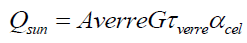 (1)
(1)
Averre: The glass Surface (m2);
G: The total direct radiation absorbed by the solar cell (W/m2);
τverre: Transmittance coefficient of the glass;
αcel : Absorption coefficient of the solar cell.
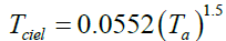
Since glass is opaque with respect to the radiation emitted by the cells, the surface of the glass becomes a radiating surface, the heat losses by radiation between the glass of the hybrid collector and the external environment are expressed as follows:
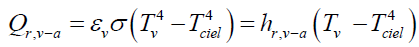 (2)
(2)
hr, v-a: The exchange coefficient by radiation is given by the following equation:
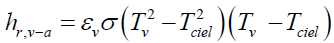 (3)
(3)
With:
 (4)
(4)
We expressed the heat losses by convection through the heat transfer equation between the glass of the hybrid collector and the external environment as follows:
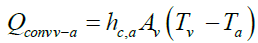 (5)
(5)
Avec:
σ: Stefan-Boltzmann constant in (W/m2°K4);
εv : Emissivity of glass;
Av: surface of the glass (m2).
hc,a: The convective heat transfer coefficient, which is a function of the wind speed (W/m2°K), is given by the following expression [17]:
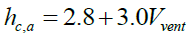 (6)
(6)
For the calculation of the thermal energy delivered by the hybrid collector, the same equation is used for the case of a thermal plane collector. For in fact, only part of the absorbed solar radiation is converted into electrical energy to useful thermal energy is:
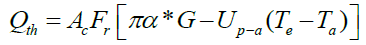 (7)
(7)
Where α*, is the factor of absorptivity [16] expressed by:
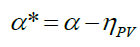 (8)
(8)
In equation (7), the useful heat gain Qth is plotted against the collector area Ac's factory, the heat extraction factor FR, solar radiation G, the coefficient of heat loss collector Up-a and the temperature difference between the coolant temperature Te and the ambient temperature Ta.
The heat extraction factor FR, is the proportion of actual gain of useful energy from the collector to the maximum possible gain useful if the entire surface of the collector was at the temperature of inlet fluid, it can be calculated as follows:
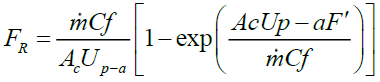 (9)
(9)
Where:
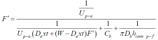 (10)
(10)
With:
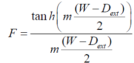 (11)
(11)
This equation determines the efficiency of the fin area between adjacent tubes, taking into account the influence of the launch tube W and the outside diameter of the tube Dtext.
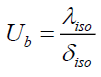
The overall coefficient of heat loss Up-a of the hybrid solar collector is the sum of losses of the forward Utop collector and outwardly Ub of edge.
In this relation, it is assumed that the heat loss coefficient forward Utop could be calculated using the empirical equation Klein as given below [17].
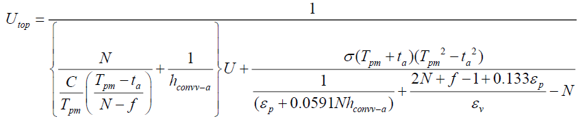 (12)
(12)
 (13)
(13)
 (14)
(14)
 (15)
(15)
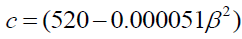
c = N is the number of blankets or layers of glass; εv emittance of coverage or the glass plate; εCu emittance of the copper layer; hconvv-a the convective heat transfer coefficient due to the wind.
 (16)
(16)
The thermal and electrical efficiency respectively, of the hybrid collector are determined by the following two expressions:
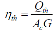 (17)
(17)
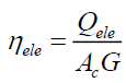 (18)
(18)
Qele: This is the power delivered by the cell is given by the following relationship:
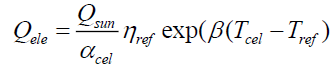 (19)
(19)
ηref : is the reference yield is measured on a reference temperature Tref taken equal to 25°C.
β: The temperature coefficient that represents the relationship between the efficiency of the solar cell and the temperature.
| PV technology | c-Si | a-Si | CdTe | CIS | CIGS |
| Temp. coefficient (°C-1) | 0.004 | 0.0026 | 0.00035 | 0.0048 | 0.0045 |
Table 1: Temperature coefficients of the different PV modules [1,18].
Presentation of the thin films PVT collectors as ANSYS Software
The ANSYS Software (version 15.0) gives the ability to predict the performance of a design where it is difficult to make accurate measurements. It can be used to create virtual prototypes and evaluate these designs before committing to the project, saving time and money. It can also be used to optimize the parameters of the system and find possible improvements in the manufacturing system without interfering with the productivity and operation of the test fixture. It used to develop the model geometry of the thin films PVT collectors; that it is represented in Figure 1.

Figure 1: Overview of the components system in Ansys Softwarev.15.
The hypothesis considered for the simulation are:
1. Water is used as coolant.
2. The problem is considered to 3D and steady state.
3. The outer surface of the glass is exposed to constant having solar flux.
4. The ambient temperature is considered constant.
5. For the flow we used in value of 0.02 Kg/s.
The first simulation is performed on a rectangular region that is formed of photovoltaic cells on the outside and of a heat exchanger tube sheet and with water as coolant. In this case, the value of the temperature of the solar cell is reduced due to the heat transfer by convection between them and the heat transfer fluid.
Figure 2 represents the boundary conditions in the system of our design of the thin films PVT collectors.

Figure 2: Boundary conditions in the system.
Figure 3 represents the Mesh Information for Case CFX of the thin films PVT collectors.

Figure 3: Mesh Information for Case CFX.
Results and Interpretations
Figure 4 shows the variation of the output temperature of the coolant in the PVT collectors based on amorphous silicon (a-Si), monocrystalline silicon (Si), cadmium telluride (CdTe), copper indium diselenide (CIS) and copper indium gallium diselenide (CIGS) as a function of a time. Which is best for the collector based on CIGS (43.2°C), as well as for the PVT collector based on CdTe (43°C) and the PVT collector at (42°C) and the Si-based PVT collector (41°C) compared to the PVT collector based on Si (39°C), for an inlet temperature set at 20°C of the coolant.

Figure 4: Variation of the output temperature of the coolant in the PVT collectors based on amorphous silicon (a-Si), monocrystalline silicon (Si), cadmium telluride (CdTe), copper indium diselenide (CIS) and copper indium gallium diselenide (CIGS).
Figure 5 shows the variation of the thermal efficiency with the time of the PVT collector based on amorphous silicon (a-Si), monocrystalline silicon (Si), cadmium telluride (CdTe), copper indium diselenide (CIS) and copper indium gallium diselenide (CIGS) respectively, whose shape is parabolic with maximum values between 12h and 14h, which it reaches a maximum around noon and decreases subsequently to a minimum value to 19h. This means that we can use the thermal energy produced by our hybrid collector throughout the day.

Figure 5: Variations in the thermal efficiency of the PVT collectors for the different PV cell type.
It can be seen that the thermal efficiency for the CIGS reaches a maximum value of the order of 57%, as well as for the PVT collector based on CdTe (56%) and the PVT collector based on CIS (55%) PVT based on amorphous silicon (52%) compared to PVT based on monocrystalline silicon (47%).
Figure 6 shows the variation in the electrical efficiency with time of the PVT collectors based on amorphous silicon (a-Si), monocrystalline silicon (Si), cadmium Telluride (CdTe), copper indium diselenide (CIS) and copper indium gallium diselenide (CIGS) respectively. The analysis of the curves obtained shows that the increase in the electrical efficiency be important when the radiation increases; we see that the maximum value of the electrical efficiency for the CIS (21.47%) is greater than that of CdTe (20.85%), Si (19.71%), CIGS (19.53%) and A-Si (9.20%).

Figure 6: Variations in the electrical efficiency of the PVT collectors based on amorphous silicon (a-Si), monocrystalline silicon (Si), cadmium telluride (CdTe), copper indium diselenide (CIS) and copper indium gallium diselenide (CIGS).
B. Analysis of the thin films PVT collectors by ANSYS Software
The simulation of the PVT collectors based on thin films solar cell (CdTe, CIS, CIGS) is performed by Ansys software simulation in 3D. The curves obtained for the temperature distribution are shown subsequently.
There is also an increase in the cell temperature (Figure 7) that advance along the PVT collectors, that is to say the input to the output of the heat transfer fluid. This is mainly due to the fluid inlet with a low temperature and extract heat energy from the cells, the average temperature from 25°C upstream (input) at 45°C downstream (outlet) of collectors.

Figure 7: Temperature Distribution of system in 3D.
Case 4: Comparison between the three types of PVT collectors:
Figures 8, 9, 10 represents the temperature evolution of the different layers (glass cover, copper layer, fluid) of the three types of PVT collectors (CdTe, CIS and CIGS).

Figure 8: Temperature Evolution of Glass layer.

Figure 9: Temperature evolution of copper layer.

Figure 10: Temperature evolution of fluid.
Figure 8 shows the evolution of the glass layer temperature of thin-layer cell-based PVT sensors (CdTe, CIS, Si and CIGS) as a function of the sensor width, a slight variation in temperature for the three materials along the X-axis; this is explained by the heat transfer which is almost identical across the sensor width which is 12 cm. The most significant temperature value is observed in the PVT sensor based on CdTe and CIS followed by that based on Si, whereas the one based on CIGS, the temperature value is the least significant.
Figure 9 shows the temperature evolution of the copper layer of PVT based on thin film cells (CdTe, CIS, Si and CIGS) as a function of sensor width, we see a decrease in the evolution Of the CIGS and Si temperature with respect to the CIS and CdTe.
Figures 8-10 shows that the temperature evolution decrease from the glass layer to the fluid due to heat transfer by convection between them and the heat transfer fluid.
The variation of the temperature of the fluid as a function of the length of the collector (Y) (in the flow direction of the fluid) of the thin film cell-based PVT collectors is represented by Figure 10 for an equal fluid inlet. At 25°C, the value at the outlet is 38.5°C, that is to say a deviation of less than 15°C.
Conclusion
In this work we have a modeling of the thermal photovoltaic collectors (PVT) based on thin film solar cells: amorphous silicon (a-Si), monocrystalline silicon (Si), cadmium telluride (CdTe), copper indium diselenide (CIS) and copper indium gallium diselenide (CIGS). The results show that the thermal efficiency reach a maximum value for the PVT collector based on CIGS (57%) and the PVT collector based on CIS gives a good electrical efficiency of the order of 21.47%. Furthermore, the output temperature of the coolant reaches a maximum value of the order of 43.2°C for the PVT collector based on CIGS compared to the other binary and ternary materials.
Nomenclature
| G | Total direct radiation absorbed by the solar cell, W/m2 |
| Absorptivity coefficient of the thin film solar cell | |
| σ | Stefan-Boltzmann constant, W/m2°K4 |
| Emissivity of glass | |
| Av | Glass surface, m2 |
| Tv | Glass temperature of the hybrid collector, °K |
| Ta | Ambient temperature, °K |
| Tcel | Cell temperature, °K |
| Ac | Surface of the PVT collector, m2 |
| G | Global illumination, W/m2 |
| C | Specific heat, 1/kg.°K |
| F | The fin efficiency |
| Dint | Inner diameter of the tube, m |
| M | Mass, kg |
| Dext | exterior diameter of the tube, m |
| ? | Mass flow, kg/s |
| Exchange coefficient by conduction, W/m2°K | |
| Exchange coefficient by convection, W/m2°K | |
| Exchange coefficient by radiation, W/m2°K | |
| FR | Extraction factor of the heat collector |
| hc-a | Coefficient of exchange by convection with the ambient, W/m2°K |
| CIGS | Copper Indium Gallium Diselenide |
| CIS | Copper Indium Diselenide |
| CdTe | Cadmium Telluride |
| a-Si | Amorphous Silicon |
References
- Mishra RK, Tiwari GN. Energy matrices analyses of hybrid photovoltaic thermal (HPVT) water collector with different PV technology. Solar Energy. 2013;91:161-73.
- Tiwari GN, Gaur A. Photovoltaic thermal (PVT) systems and its applications, 2nd International Conference on Green Energy and Technology. 2014.
- Tiwari GN, Mishra RK, Solanki SC. Photovoltaic modules and their applications: A review on thermal modeling. Applied Energy 2011;88(7):2287-304.
- Chopra KL, Paulson PD, Dutta V. Thin-Film Solar Cells: An Overview. Prog Photovolt Res Appl. 2004;12:69-92.
- Badgujar AC, Dhage SR, Joshi SV. Process parameter impact on properties of sputtered large-area Mo bilayers for CIGS thin film solar cell applications. Thin Solid Films. 2015;589:79-84.
- Green MA, Emery K, Hishikawa Y, et al. Solar efficiency table (version 39). Prog Photovolt Res Appl. 2012;20:12.
- Zhou D, Zhu H, Liang X, et al. Sputtered molybdenum thin films and the application in CIGS solar cells. Applied Surface Science. 2016;362:202-9.
- Wuerzan R, Eickea A, Kesslera F, et al. CIGS thin-film solar cells and modules on enamelled steel substrates. Solar Energy Materials & Solar Cells. 2012;100:132-7.
- Khan M, Kumar S, Alsalhi MS, et al. Morphology and non-isothermal crystallization kinetics of CuInS2nanocrystals synthesized by solvo-thermal method. Mater Charact. 2012;65:109 e14.
- Zhuang MX, Wei AX, Zhao Y, et al. Morphology-controlled growth of special nanostructure CuInS2 thin films on an FTO substrate and their application in thin film solar cells. International Journal of Hydrogen Energy. 2015;4:806-14.
- Mandal M, Choudhury S, Begum T. Substrate temperature dependent optical and structural properties of vacuum evaporated CdTe thin films. European Scientific Journal. 2014;10(3):1857-7431.
- Parida B, Iniyan S, Goic R. A review of solar photovoltaic technologies. Renew Sustainable Energy Rev. 2011;15(3):1625-36.
- Moradi K, Ali Ebadian M, Cheng-Xian L. A review of PV/T technologies: Effects of control parameters. International Journal of Heat And Mass Transfer. 2013;64:483-500.
- Touafek K, Haddadi M, Malek A. Modeling and Experimental Validation of a New Hybrid Photovoltaic Thermal Collector. IEEE Transactions on Energy Conversion. 2011;26(1):176-83.
- Touafek K, Haddadi M, Malek A. Numerical simulation of the thermal behavior of thermal solar photovoltaic hybrid collector. Reviews of Renewable Energies. 2008;11(1):153-65.
- Touafek K. Study of a Hybrid Photovoltaic Thermal Solar collector. Magister Thesis. National Polytechnic School. Algiers. 2005.
- Duffie JA, Beckman WA. Solar Engineering of Thermal Processes. New York, Etats-Unis, Wiley-Interscience. 1980.
- Adham Makki, Siddig O, Hisham S. Advancements in hybrid photovoltaic systems for enhanced solar cells performance. Renewable and Sustainable Energy Reviews. 2015;41:658-84.